47
Pneumatic installation
9 PNEUMATIC INSTALLATION
9.1 Safety instructions
DANGER!
Riskofinjuryfromhighpressureintheequipment/device.
▶ Beforeworkingonequipmentordevice,switchothepressureanddeaerate/drainlines.
WARNING!
Riskofinjuryfromimproperinstallation.
▶ Installation may be carried out by authorized technicians only and with the appropriate tools.
Riskofinjuryfromunintentionalactivationofthesystemandanuncontrolledrestart.
▶ Secure system from unintentional activation.
▶ Following installation, ensure a controlled restart.
9.2 Connecting the device pneumatically
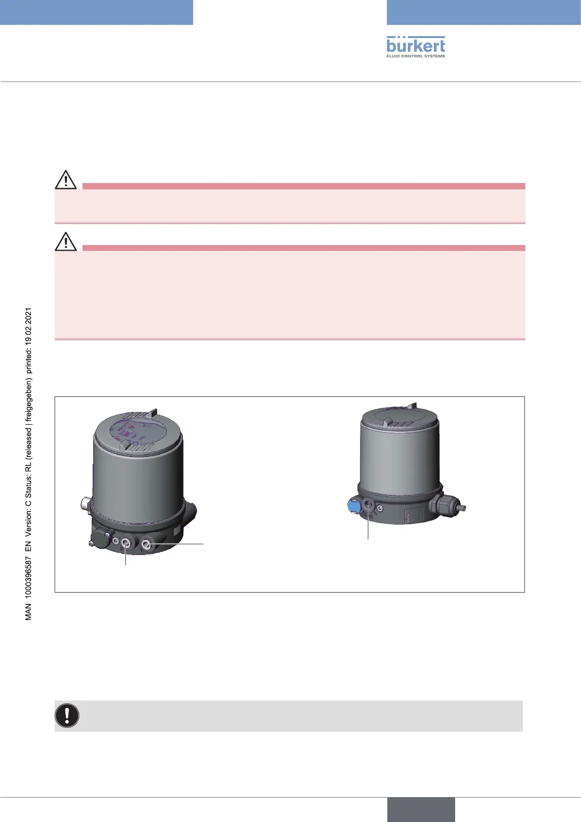
Pilot air port
(label: 1)
Exhaust air port
(label: 3)
Additional exhaust air port (label: 3.1)
only for Type 23xx and 2103
with pilot valve system
forhighairowrate(actuatorsizeø130)
Figure 31: Pneumatic connection
Procedure:
→ Connect the control medium to the pilot air port (1) (3 – 7 bar; instrument air, free of oil, water and dust).
→ Attach the exhaust air line or a silencer to the exhaust air port (3)
and, if available to the exhaust air port (3.1)
Caution: (Exhaustairconcept):
▶ In compliance with degree of protection IP67, an exhaust air line must be installed in the dry area.
english
Type 8694 REV.2