26
Control and display elements
7 CONTROL AND DISPLAY ELEMENTS
The following chapter describes the operating statuses as well as the control and display elements of the positioner.
Further information on the operation of the positioner can be found in the chapter entitled
“13Start-up”.
7.1 Operating state
TooperatetheDIPswitchesandbuttons,makesurethatthelocalcontrollockisdeactivated/
unlocked(factorysetting):withcommunicationsoftwareoreldbuscommunication.
AUTOMATIC(AUTO)
Normal controller mode is implemented and monitored in AUTOMATIC operating state.
MANUAL
In MANUAL operating state the valve can be opened and closed manually via the buttons.
DIP switch 4 can be used to switch between the two operating states AUTOMATIC and MANUAL.
ON DIP
1
2 3 4
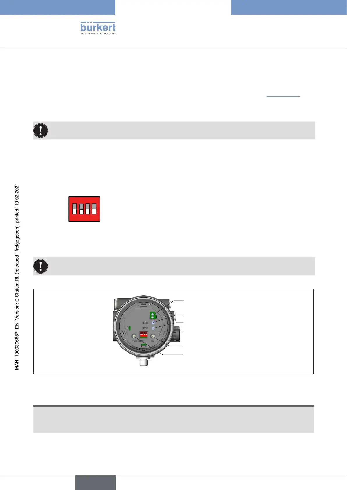
7.2 Control and display elements of the positioner
TooperatetheDIPswitchesandbuttons,makesurethatthelocalcontrollockisdeactivated/
unlocked(factorysetting):withcommunicationsoftwareoreldbuscommunication.
1 2 3 4
ON DIP
Communications
interface
LED 1
LED 2
DIP switches
Button 1
Button 2
Figure 9: Description of control elements
The positioner features 2 buttons, 4-pole DIP switches and 2 LEDs as a display element.
ATTENTION!
Breakageofthepneumaticconnectionpiecesduetorotationalimpact.
▶ When unscrewing and screwing in the body casing or transparent cap, do not hold the actuator of the
process valve but the basic housing.
→ To operate the buttons and DIP switches, unscrew the transparent cap.
english
Type 8694 REV.2