51
Electrical installation 24 V DC
10.2.2 Connection of the positioner Type 8694
→ Connect the pins according to the model of the positioner.
Input signals of the control center (e.g. PLC), circular plug M12 x 1, 8-pin
Pin Wirecolor
23)
Conguration Externalcircuit/signallevel
1
2
white
brown
Set-point value + (0/4 – 20 mA)
Set-point value GND
1
2 GND
see table connection type
3-wire or 4-wire
+ (0/4 – 20 mA)
5
6
grey
pink
Digital input +
Digital input GND
5 + 0 – 5 V (logical 0)
10 – 30 V (logical 1)
identical to pin 3 (GND)
Table 19: Pin assignment, input signals of the control center, circular plug M12 x 1, 8-pin
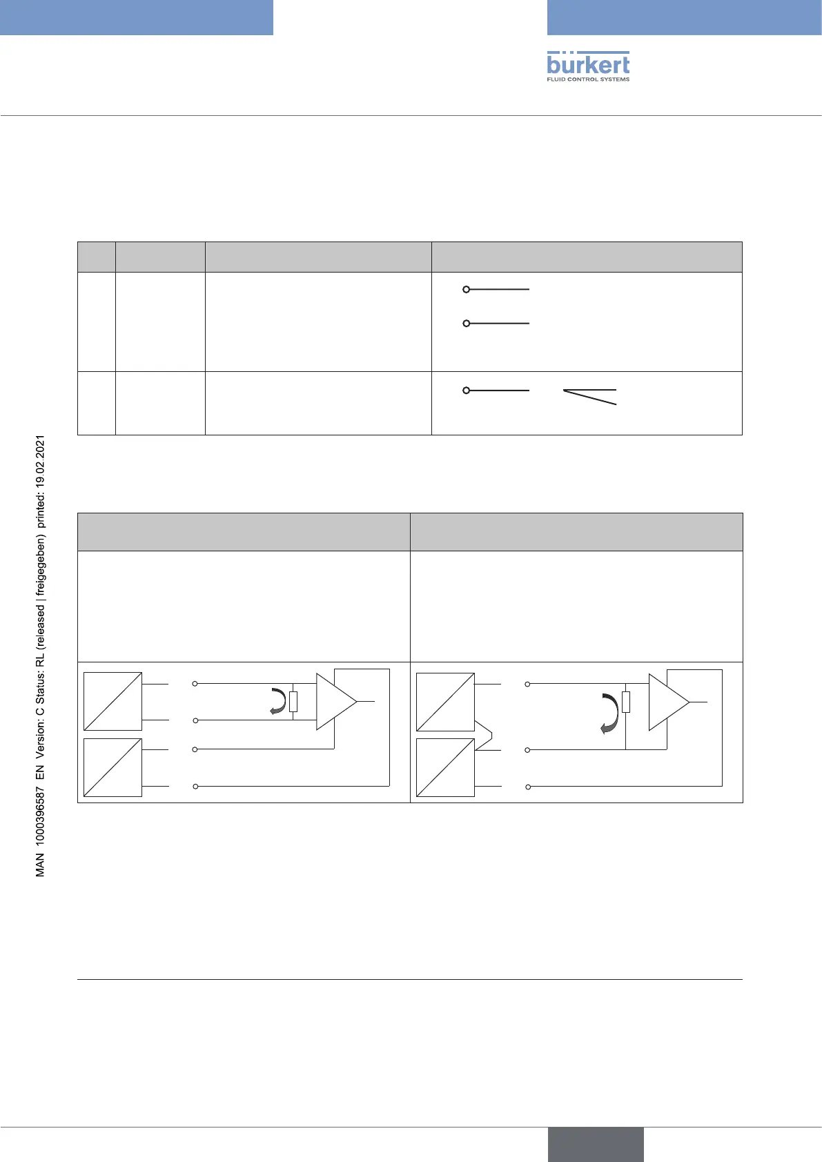
Connection type 3-wire or 4-wire (setting via communication software):
Connectiontype4-wire(factorysetting) Connectiontype3-wire
Theset-pointvalueinputisdesignedasadier-
ential input, i.e. the GND lines of the set-point value
input and the supply voltage are not identical.
Note: If the GND signals of the set-point value input
and the supply voltage are connected, the 3-wire
connection type must be set in the software.
The set-point value input is related to the GND line
of the supply voltage, i.e. setpoint input and supply
voltage have a common GND line.
1
2
0/4-20 mA
3
4
GND
+24 V DC
+
+
U
I
1
0/4-20 mA
3
4
GND
+24 V DC
+
+
U
I
Table 20: Connection type
23) The indicated colors refer to the connecting cable available as an accessory (919061)
english
Type 8694 REV.2