32
Control and display elements
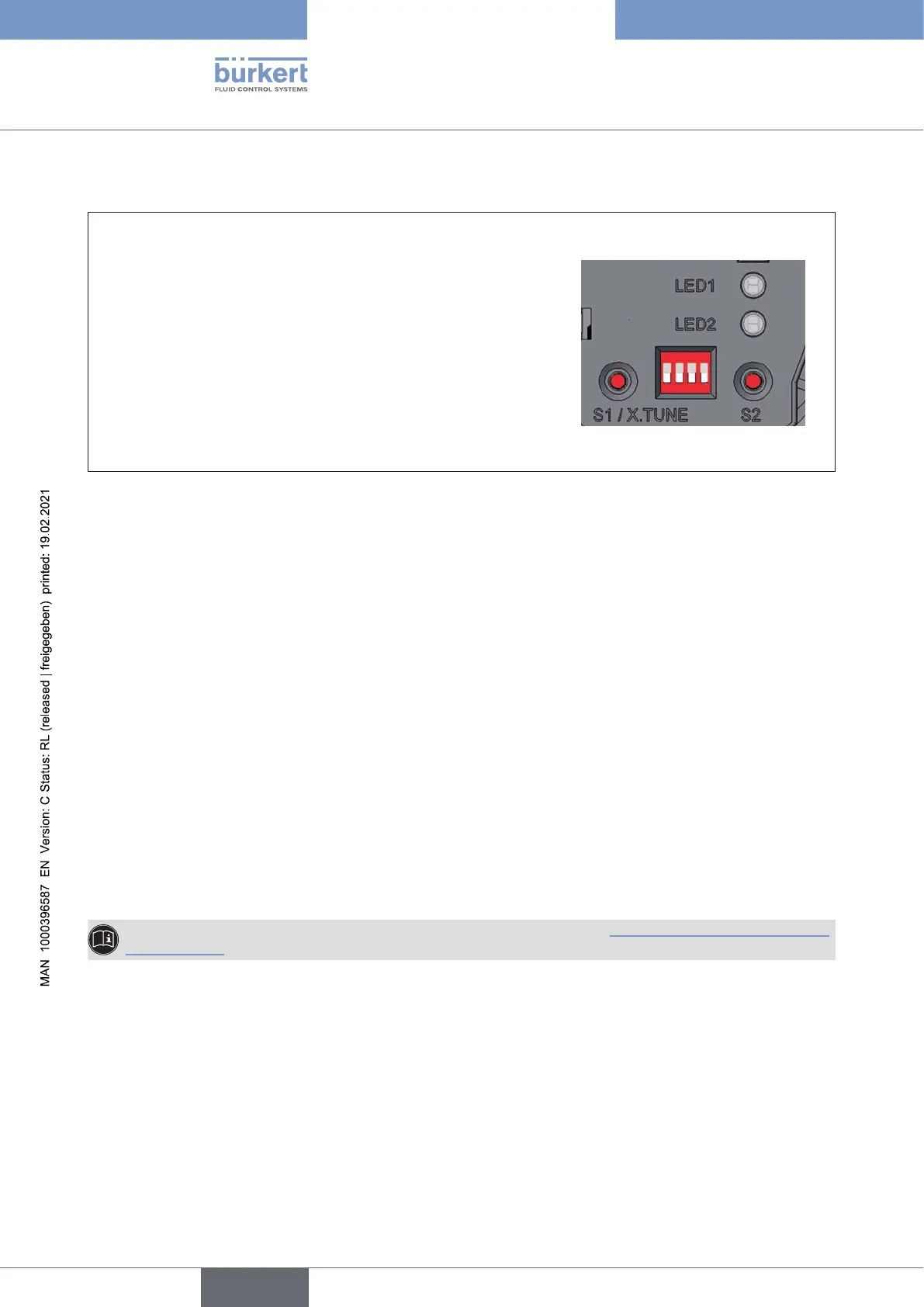
7.5 Display of the LEDs
LED 1
(RGB)
Display of the device status and valve
position
LED 2
(green)
Display of the bus status
Feedback during pressing buttons to start
functions
• X.TUNE
• Device restart
• Reset to factory settings
Figure 17: LED display
7.5.1 Device status display
The LED 1 (RGB) show the device status.
The user can set the following LED modes for the display of device status and valve position.
• NAMUR mode
• Valve mode
• Valve mode with warnings (factory setting)
• Fixed color
• LEDo
The LED mode and the colors of the valve position can be set with the Bürkert Communicator.
IO-Link:
The LED mode and the colors of the valve position can be also set with an acyclic parameter (see para-
meter list).
The description for setting the LED mode can be found in the chapter “16.2.10SettingtheLEDmode,
devicestatus” .
english
Type 8694 REV.2