52
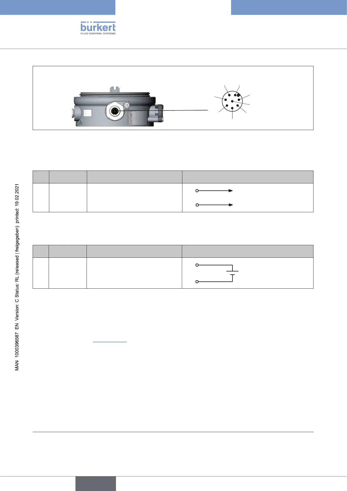
Electrical installation 24 V DC
6
1
7
5
4
3
2
8
View without body
casing
Circular plug
M12 x1, 8-pin
Figure 36: Circular plug M12 x 1, 8-pin
Output signals to the control center (e.g. PLC), circular plug M 12 x 1, 8-pin
(required for analogue output variant only)
Pin Wirecolor
24)
Conguration Externalcircuit/signallevel
8
7
red
blue
Analogue position feedback +
Analogue position feedback GND
8
7 GND
+ (0/4 – 20 mA)
Table 21: Pin assignment, output signals of the control center, circular plug M12 x 1, 8-pin
Operating voltage (circular plug M12 x 1, 8-pin)
Pin Wirecolor
24)
Conguration Externalcircuit
4
3
yellow
green
+ 24 V
GND
4
3
24 V DC ± 25 %
max. residual ripple 10 %
Table 22: Pin assignment, operating voltage (circular plug M12 x 1, 8-pin)
When the supply voltage is applied, the positioner is operating.
→ Make the required basic settings and actuate the automatic adjustment of the positioner, as described in
the chapter entitled “13Start-up”.
24) The indicated colors refer to the connecting cable available as an accessory (919061)
english
Type 8694 REV.2