Programmable HV Power Supply
Revision 19
n
CAEN
T o o l s f o r D i sc o v e r y
2.4 Front panel connections
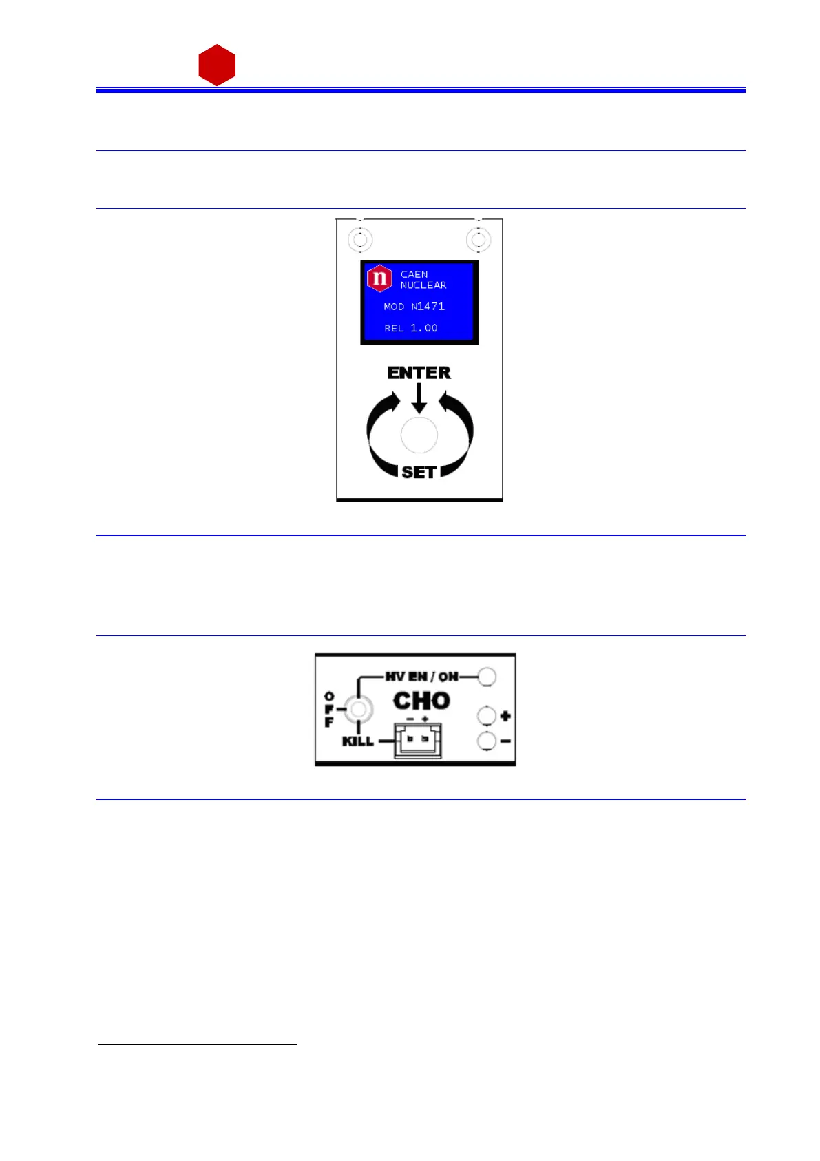
2.4.1 Local control section
1
Fig. 2.4: Local control panel
Local settings monitoring
Parameter and Mode setting
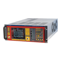
2.4.2 Channel control section
Fig. 2.5: Channel control panel and Kill scheme
Channel Enable and turning OFF/KILL
2
The channel is KILLED either as the +/- contacts are open or as a
+4÷6Vdc voltage is fed to pin - (see note)
1
Not available on Mod. N1471AR
2
OFF: Channel turned off according to RAMP DOWN setting; KILL: Channel turned off at fastest availabl e rate