Programmable HV Power Supply
Revision 19
n
CAEN
T o o l s f o r D i sc o v e r y
A s chematic diagram of the Interlock input is s hown in the figure above, where the diode is part of optocoupler
sta ge.
Interlock means that channels are hardware disabled. The interlock opera ti on is expla i ned by the foll owi ng
tabl e:
Table 2.2: Interlock operation
INTERLOCK MODE (§ 3.1.1)
voltage level (0÷1V, ~5mA current) between pin 2 and pin 3
short circuit pin 1 w ith pin 2, and pin 3 w ith pin 4
voltage level (4÷6V, ~5mA current) between pin 2 and pin 3
The front panel Interlock LED is ON when the INTERLOCK i s enabled; as INTERLOCK is enabled, cha nnels are
turned off at the fastes t availa ble rate, rega rdles s the RAMP DOWN s etting.
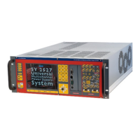
2.4.4 Remote communication control section
3
Fig. 2.10: Remote communication control and RS485 I/O – RS232 IN electrical scheme
RS485 Input
4
; adaptable to RS232 standard
USB2.0 compliant realized via USB ↔ RS232 FT232BM converter
3
Not available on Mod. N1471AL
4
RS 485 Serial Port Interface allow s to control up to 32 modules connected by a tw isted pair cable; the first and last modules must
be terminated, see § 4.2.1.