Programmable HV Power Supply
Revision 19
n
CAEN
T o o l s f o r D i sc o v e r y
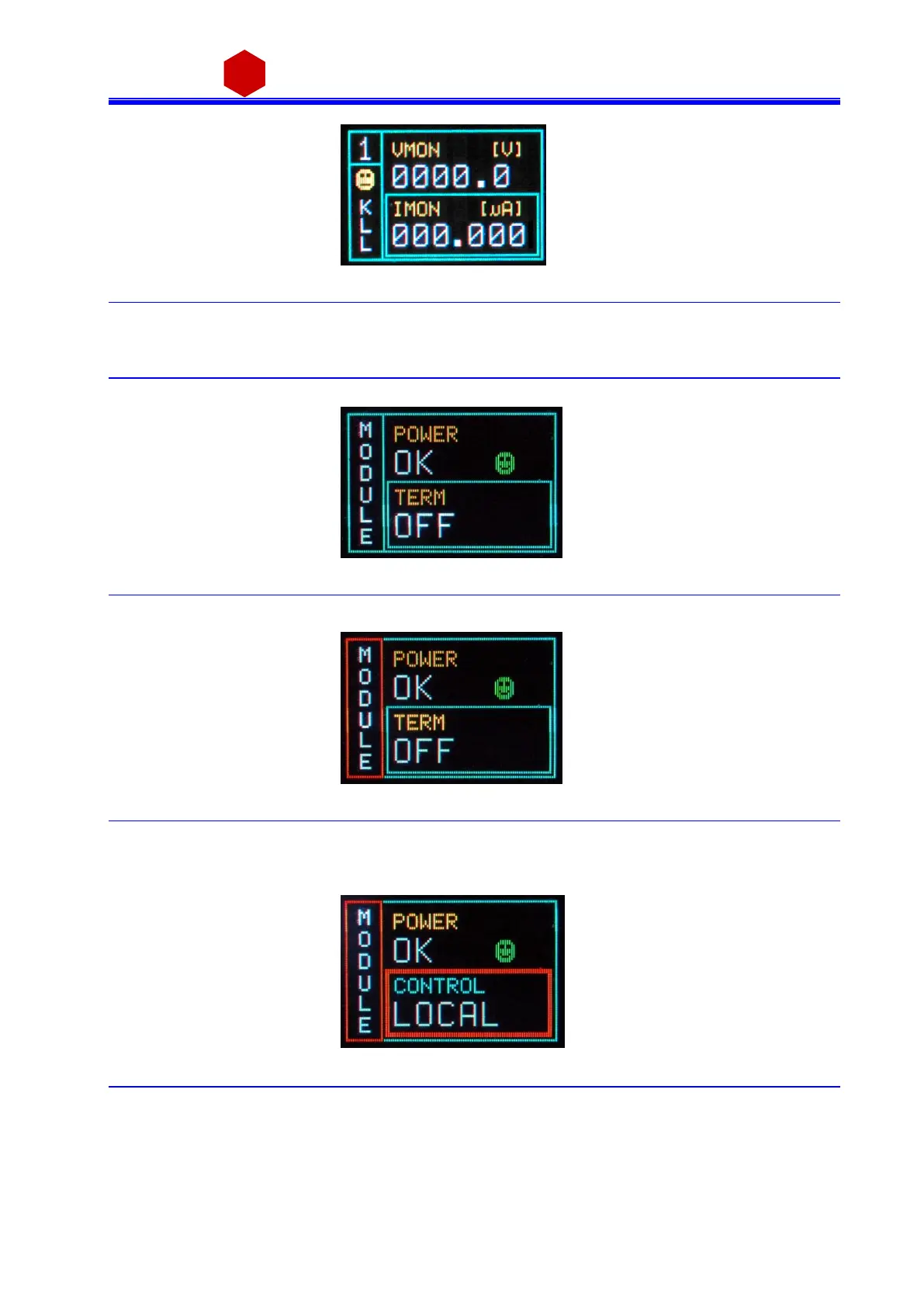
Fig. 3.4: Channel KILL status screen
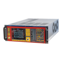
3.2.2 Module settings
Modul e setti ngs a re general board settings ; turn the TUNE ROTARY SWITCH unti l this s creen i s shown:
Fig. 3.5: Mode settings status screen
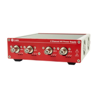
Push the TUNE ROTARY SWITCH i n order to access MODULE parameters; the MODULE frame becomes red:
Fig. 3.6: Mode settings access screen
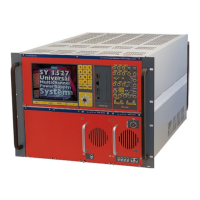
The TUNE ROTARY SWITCH allows to s el ect the pa rameter to be s et; turn the ROTARY SWITCH until such
pa ra meter is displayed (for example CONTROL), then select it by pushing the ROTARY SWITCH (the parameter is
shown wi th a red frame as long as i t i s active):
Fig. 3.7: Mode settings edit screen
Select the desired value by turning the TUNE ROTARY SWITCH and confi rm it by pushi ng the s witch its elf.