Programmable HV Power Supply
Revision 19
n
CAEN
T o o l s f o r D i sc o v e r y
- Da ta bits: 8
- Parity: none
- stop bit: 1
- Flow control: Xon Xoff
It i s also possible to build a daisy chain of up to 32 N1471’s, with the first modul e connected to the PC RS232
port and the subsequent ones daisy chained through the COMM IN/OUT, as expl a ined i n § 2.4.4; i n thi s case
communication with the chained modules is achieved through the USB - RS485 Communication Protocol . All
modules must be assigned a LOCAL BUS ADDRESS (see § 3.1.1) different from one another a nd the l ast one must
be terminated (s ee § 4.2.1).
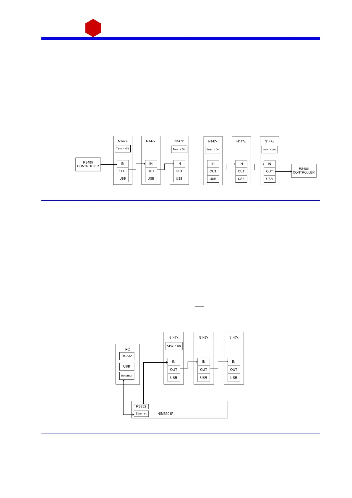
3.4.1.3 RS485 communication
Fig. 3.30: RS485 communication diagram
The COMM IN / OUT connectors implement a RS485 type LOCAL BUS which allows to build a 32 modules da i sy
cha i n. Thi s can be achi eved through the followi ng steps :
Connect the connector OUT of a modul e to corres ponding the IN connector of the next one
As si gn to each module a di fferent a ddress (LOCAL BUS ADDR); s ee § 3.1.1
Ensure that the LOCAL BUS BIT RATE i s the s ame for all modules; s ee § 3.1.1
Termina te the fi rs t and the l a st module in the chai n (see § 4.2.1)
The module control can be done i n one of the fol lowi ng ways :
o by connecting a RS485 control ler to the fi rs t module’s COMM IN port
o by connecting a RS485 controller to the las t module’s COMM OUT port
Communication with the chained modules is achieved only through the USB - RS485 Communica ti on Protocol ,
see § 3.4.2.
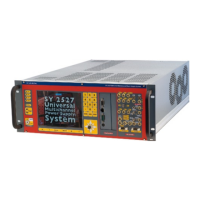
3.4.1.4 Ethernet communication
Fig. 3.31: Ethernet communication diagram