Programmable HV Power Supply
Revision 19
n
CAEN
T o o l s f o r D i sc o v e r y
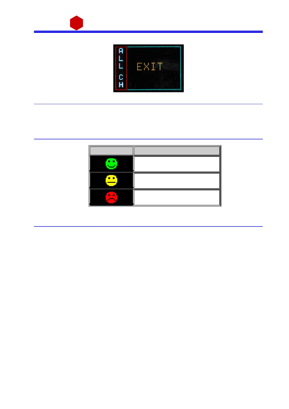
In order to go to individual cha nnel settings , the EXIT parameter has to be selected
Fig. 3.27: Group EXIT screen
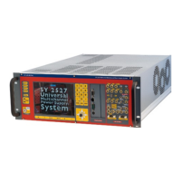
3.2.3.2 Smileys
Three types of Smi leys i n the dis pl ay indicate:
Table 3.1: Smileys list
3.3 Current monitor offset calibration
The module is calibrated by i ntroducing a positive offset on the current monitor. This type of calibration a l lows
to moni tor very l ow current thus removing possible i s s ues due to components a nd working tempe ratures
rel ated negative offsets. The absolute va lue of delivered current can be quantified by following the steps below:
1) Turn on the module, after a warm-up of about 30 minutes with operating voltage and l oa d disconnected
(no li nk between N1471 a nd detectors ) then read the monitored current value Imon = I1 (offs et)
2) Turn off the channel and connect the load
3) Turn on the channel with the s a me vol tage s et a s point 1)
4) Wait a few mi nutes and read again the current va l ue monitor Imon = I2 (offs et + Iout)
5) The va lue of current output i s equa l to the difference between I2 a nd I1 (Iout = I2 – I1)
Leakage currents equal to 1 nA / kV s ha ll be tol erated; e.g. Vout = 4000V, Imon = +6 nA (2nA Offs et + 4nA
current l eakage/4KV). The offset introduced is equal to 20nA for high range and 2nA for l ow range wi th output
vol tage a t 10% of full s cal e and 20 °C tempera ture.