Programmable HV Power Supply
Revision 19
n
CAEN
T o o l s f o r D i sc o v e r y
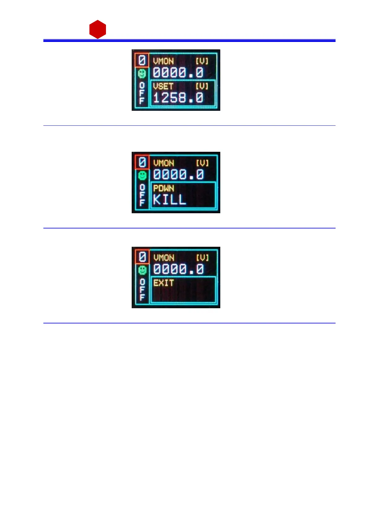
Fig. 3.16: Channel VSET de-select screen
It i s now possible to set a nother parameter; note that the POWER DOWN and IMRANGE setting has not digits to
be edited, but two opti ons, TRIP/KILL a nd HIGH/LOW respectivel y:
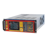
Fig. 3.17: Channel KILL screen
In order to access another channel, the EXIT parameter ha s to be sel ected
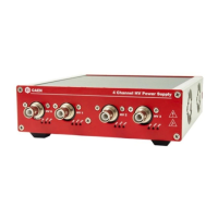
Fig. 3.18: Channel EXIT screen
Now by turni ng the TUNE ROTARY SWITCH a nother channel number to be set ca n be selected.
If CONTROL MODE (s ee § 3.4) i s set to REMOTE, the left lower row reports DIS (Disabled), since the channel can
be accessed only via the serial links (see § 3.4.1). If the INTERLOCK MODE i s changed while one cha nnel i s ON,
the channel i s turned OFF and the left lower row reports ILK (Interl ock); i f the channel is OFF, i t can not be
turned ON, until it i s ena bled a ccordi ng to the Interlock logic (s ee § 2.4.3.2).