Programmable HV Power Supply
Revision 19
n
CAEN
T o o l s f o r D i sc o v e r y
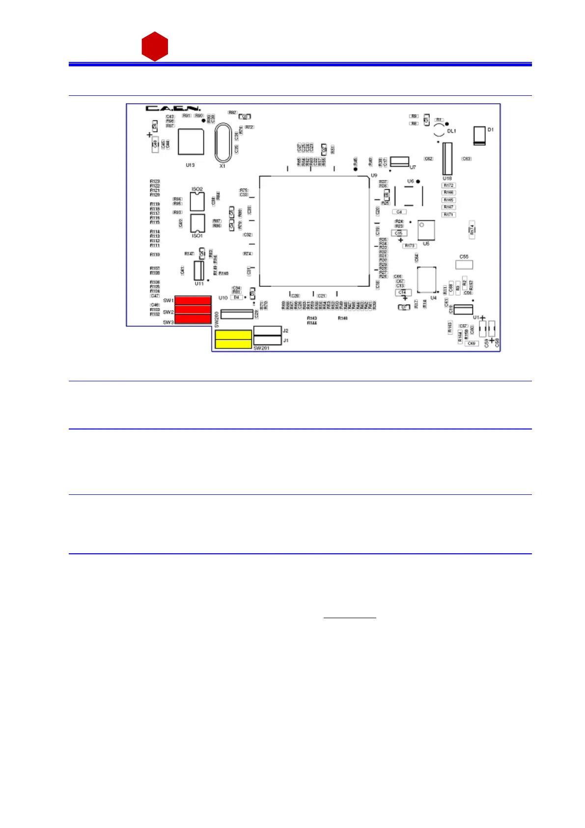
4.2 Internal switches
Fig. 4.3: Dip switch position
4.2.1 Local Bus termination
The SW[1..3] s witch placed on the Microcontroller board inside the module (behind the Remote communication
control section, see § 2.4.4), allows to terminate the Local Bus for daisy chain purposes (see § 3.4.1.2); dot NOT
vi s ible = Termination ON.
4.2.2 RS485 – RS232 conversion
The SW[200, 201] s witch placed on the Microcontroller board inside the module, a llows to adapt RS485 signa ls
to RS232; dot vi s ible = Ada ptation ON.
4.3 Grounding specifications
The Mod. N14xx cha nnels share a common floating return (FAGND), insulated from the crate ground (AGND).
This feature allows on-detector grounding, thus a voiding l oops which ma y increase nois e l evel . FAGND and
AGND may be connected, by short circuiting C21 jumper pins on the motherboard (s ee fi gure below). The
protection s hield must be s crewed off in order to access C21 (see 4.1). Please note tha t ol der versions of the
N14xx may not ha ve C21 jumper ins tal l ed; contact info@caen.it for detai l s.