Programmable HV Power Supply
Revision 19
n
CAEN
T o o l s f o r D i sc o v e r y
3.2 Local Control
Ins ert the unit i nside a powered NIM crate, a nd switch it ON. At the power the Display shows for a few seconds
the following screen.
Fig. 3.1: Welcome screen
At this point the module is ready to be operated locally. The TUNE ROTARY SWITCH (see § 2.4) i s lit up as long as
Local Control is ena bled.
3.2.1 HV connection
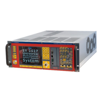
Verify the channels polarity (polarity setting is explained i n § 4.1) checking that the polarity LEDs are s wi tched
on according to the programmed configuration (see § 2.4.1); verify the HV_EN/OFF/KILL 3 POS. SWITCH of each
cha nnel i s s et to OFF; the Dis pl a y will show the foll owi ng mes s a ge i n the left lower row:
Fig. 3.2: Channel OFF status screen
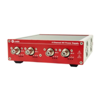
now connect the HV cable linking the outputs to the loads to be supplied and enable the HV outputs switchi ng
the HV_EN/OFF/KILL 3 POS. SWITCH in the HV_EN position; the Display will show the following mess a ge in the
left lower row:
Fig. 3.3: Channel ON status screen
The KILL position of the HV_EN/OFF/KILL 3 POS. SWITCH allows to turn off the module at the fas test ava i la ble
rate; the Dis pl ay will s how the foll owi ng mes sa ge i n the left lower row: