Programmable HV Power Supply
Revision 19
n
CAEN
T o o l s f o r D i sc o v e r y
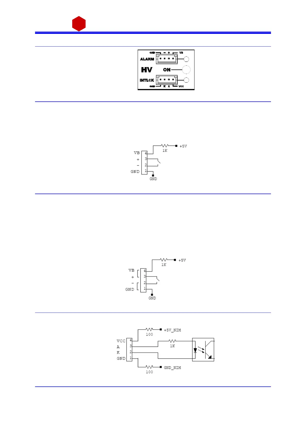
2.4.3 HV Status control section
Fig. 2.6: N1471 HV Status control panel
HV On enabled (at least one channel ON)
Alarm status signaled (active LOW)
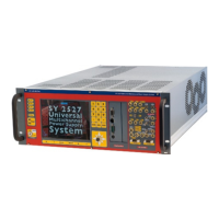
2.4.3.1 Alarm signal
Fig. 2.7: N1470 ALARM electrical scheme
As a n Al arm condition is detected (see § 3.5.3.1 and § 3.5.4.1) pins 2 and 3 (- a nd +) are closed; the contact can
be us ed to switch an external device s upplied by an external source, otherwise the VB a nd GND references can
be us ed to provide a TTL compatibl e level on pi n 2 a nd 3.
In the first ca s e (externa ll y s upplied device) the ma ximum al lowed ratings a re:
Maximum vol ta ge between + a nd -: 12V
Maximum sink current a cros s + a nd -: 100mA
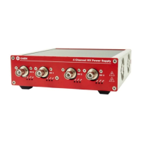
In the l atter case, in order to produce a TTL compatible Alarm Out, pin 3 (+) must be connected with pi n 4 (VB)
and pin 1 (GND) wi th pi n 2 (-); see the di agram bel ow:
Fig. 2.8: N1470 ALARM TTL configured
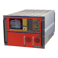
2.4.3.2 Interlock signal
Fig. 2.9: N1470 INTERLOCK electrical scheme