Programmable HV Power Supply
Revision 19
n
CAEN
T o o l s f o r D i sc o v e r y
TABLE OF CONTENTS
1 General description ..............................................................................................................................................................5
1.1 Overview .......................................................................................................................................................................5
2 Technical specifications......................................................................................................................................................6
2.1 Packaging .....................................................................................................................................................................6
2.2 Power requirements ....................................................................................................................................................6
2.3 Front and back panel ..................................................................................................................................................8
2.4 Front panel connections .......................................................................................................................................... 10
2.4.1 Local control section ........................................................................................................................................... 10
2.4.2 Channel control section...................................................................................................................................... 10
2.4.3 HV Status control section .................................................................................................................................. 11
2.4.3.1 Alarm signal .................................................................................................................................................. 11
2.4.3.2 Interlock signal .............................................................................................................................................. 11
2.4.4 Remote communication control section .......................................................................................................... 12
2.5 Rear panel connections........................................................................................................................................... 13
2.5.1 HV Channel Output............................................................................................................................................. 13
2.6 Imon Zoom ................................................................................................................................................................ 13
2.7 Technical specifications table................................................................................................................................. 14
3 Operating modes ................................................................................................................................................................ 15
3.1 Programmable parameters ..................................................................................................................................... 15
3.1.1 Boards parameters ............................................................................................................................................. 15
3.1.2 Channel settings.................................................................................................................................................. 16
3.2 Local Control ............................................................................................................................................................. 17
3.2.1 HV connection ..................................................................................................................................................... 17
3.2.2 Module settings ................................................................................................................................................... 18
3.2.3 Channel settings.................................................................................................................................................. 19
3.2.3.1 Group Settings .............................................................................................................................................. 22
3.2.3.2 Smileys ......................................................................................................................................................... 24
3.3 Current monitor offset calibration........................................................................................................................... 24
3.4 Remote Control......................................................................................................................................................... 25
3.4.1 Serial Links........................................................................................................................................................... 25
3.4.1.1 USB communication ..................................................................................................................................... 25
3.4.1.2 RS232 communication .................................................................................................................................. 25
3.4.1.3 RS485 communication .................................................................................................................................. 26
3.4.1.4 Ethernet communication ............................................................................................................................... 26
3.4.2 Communication Control...................................................................................................................................... 27
3.4.2.1 Remote Control: Main Menu ......................................................................................................................... 27
3.4.2.2 Remote Control: General Menu .................................................................................................................... 28
3.4.2.3 Remote Control: Channels Menu .................................................................................................................. 28
3.4.2.4 Remote Control: firmw are upgrade ............................................................................................................... 29
3.4.2.5 Remote Control: format EEPROM ................................................................................................................ 30
3.4.2.6 Remote Control: Current offset calibration .................................................................................................... 30
3.5 USB - RS485 Communication Protocol ................................................................................................................ 31
3.5.1 Command Format ............................................................................................................................................... 31
3.5.2 Format of response string.................................................................................................................................. 31
3.5.3 MONITOR commands related to the Channels ............................................................................................. 32
3.5.3.1 Meaning of STATUS bits (value read in decimal Format) ............................................................................. 32
3.5.4 MONITOR commands related to the module ................................................................................................. 33
3.5.4.1 Meaning of Board Alarm bits......................................................................................................................... 34
3.5.5 SET commands related to the Channels ........................................................................................................ 34
3.5.6 SET commands related to the module ............................................................................................................ 34
4 Internal Settings.................................................................................................................................................................. 35
4.1 Polarity selection ...................................................................................................................................................... 35
4.2 Internal switches ....................................................................................................................................................... 37
4.2.1 Local Bus termination ......................................................................................................................................... 37
4.2.2 RS485 – RS232 conversion .............................................................................................................................. 37
4.3 Grounding specifications ......................................................................................................................................... 37
4.3.1 Safety Earth connection ..................................................................................................................................... 38
LIST OF FIGURES
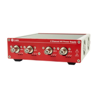
Fig. 1.1: Mod. N1471 4 Channel Programmable HV Power Supply ........................................................................................5
Fig. 2.1: Backplane NIM connector................................................................................................................................................7
Fig. 2.2: Mod. N1471 series front panel (std, A, B, AL, AR) ......................................................................................................8
Fig. 2.3: Mod. N1471 series back panel (std., A, B) ...................................................................................................................9
Fig. 2.4: Local control panel ......................................................................................................................................................... 10
Fig. 2.5: Channel control panel and Kill scheme ...................................................................................................................... 10
Fig. 2.6: N1471 HV Status control panel ................................................................................................................................... 11