60 TYPE R Radio Production System System Elements
CORE LAYOUT
The UR6500 Type R core is designed
to provide the DSP, Routing &
Control for up to three consoles. In
addition it has a base level of I/O and
GPIO and one or two optional AoIP
interface devices fitted internally
allowing a large amount of stream
connectivity with other AoIP devices.
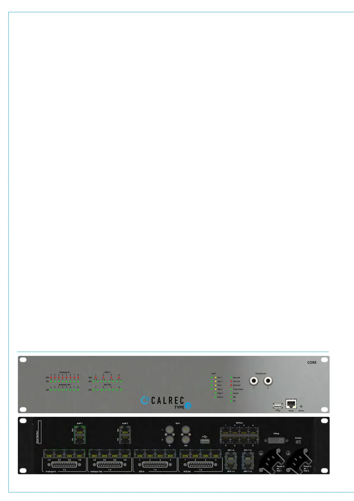
The image below shows the front and
back views of the Type R core unit.
The front of the core displays on the left
hand side the LED signal status indicators
for the Analogue and AES inputs and
outputs. In addition the 48V phantom
power LED status indicators for the
analogue inputs and the SRC LED status
indicators are shown.
On the right hand side are shown the
AoIP LED status indicators and a further
column of System LED status indicators
and to the right of these are two 6.35mm
(1/4”) headphone sockets for monitoring
usage. Next to these are an Ethernet
Setup port and USB connector.
The Setup port is used to configure the
Core whilst the USB connector is used
to recover/reinitialise the core system
from a USB memory stick in the event of
connection failure . At the far right is a
Reset switch which restarts the processor
without altering any stored settings.
The rear of the core is arranged into a top
row and a bottom row.
UR6500 TYPE R CORE - FRONT AND BACK VIEWS
The top row contains the external system
connections which from left to right are:-
AoIP1 and AoIP2 RJ45 interfaces which
are connected to internally fitted optional
US6493 AoIP devices (with redundant
Primary and Secondary connections) .
Each of these devices can provide up to
256 channels of streamed audio in either
direction. Next to these are a set are 4
BNC connectors labelled Sync 1/2 In and
1/2 Out. These are discussed in the Sync
section.
To the right of the BNC connectors are
a secondary USB connector and a block
of 8 RJ45 connectors which connect to
the various surfaces via PoE+ switches.
Typically each of these connect to a
separate PoE+ switch interfacing to a
number of Fader, LSP and SSP panels.
More than one connection is usually made
to each console area to provide control
diversity. For instance a 24 fader console
may be powered from two PoE+ switches
connected back to the core, with each
switch powering and data transferring
to/from 2 x IM6413 fader panels and 2 x
MU6411 Large Soft Panels.
Further to the right is a DVI debug port
which is reserved for development use
along with a PRI/SEC switch.
The bottom row is dedicated to I/O, GPIO
and Power. There are 4 x 25 way ‘D’ Type
connectors carrying audio using AES59/
Tascam® pinout format and the audio is
also carried as pairs of Analogue inputs
or outputs or AES I/O ports on 4 x RJ45
connectors per 25 way ’D’ type connector.
The four connector areas from left to right
provide:- 8 Mic/Line Analogue inputs
with phantom power, 8 Analogue Line
Outputs, 4 AES Input ports with SRC and
4 AES Output ports.
Further to the right are 4 x RJ45
connectors for GPIO interfacing.
The upper two connectors each provide
6 x GPI opto input circuits each and the
lower two connectors provides 6 x GPO
opto output circuits each.
On the bottom row of the core are 2 x IEC
power sockets labelled PSU 1 and PSU 2,
either of which can power the console.
Together they provide power redundancy.
The IEC inputs should be fed from
separate AC sources to protect against
external power loss. In the event that only
one AC outlet is available, power should
be fed via an IEC Y-Split cable to provide
redundancy against internal PSU failure.
Metal clips provide retention to further
protect the IEC connectors from working
loose. These clips fit snug around large
IEC connectors with screw in terminals
inside for wiring. The clips may not provide
adequate retention on their own for some
pre-fabricated IEC connector types. If
there is concern over the connectors
working loose during transit, we
recommend that IEC sockets with built in
latching are used.