Chapter 2
2-3
2.1.3 Print Signal Sequence
0017-4696
iPF650 / iPF655
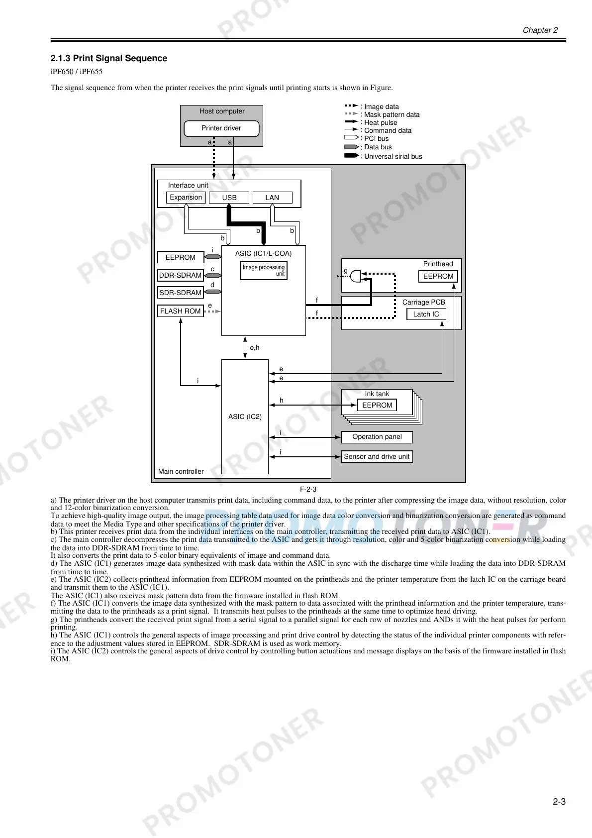
The signal sequence from when the printer receives the print signals until printing starts is shown in Figure.
F-2-3
a) The printer driver on the host computer transmits print data, including command data, to the printer after compressing the image data, without resolution, color
and 12-color binarization conversion.
To achieve high-quality image output, the image processing table data used for image data color conversion and binarization conversion are generated as command
data to meet the Media Type and other specifications of the printer driver.
b) This printer receives print data from the individual interfaces on the main controller, transmitting the received print data to ASIC (IC1).
c) The main controller decompresses the print data transmitted to the ASIC and gets it through resolution, color and 5-color binarization conversion while loading
the data into DDR-SDRAM from time to time.
It also converts the print data to 5-color binary equivalents of image and command data.
d) The ASIC (IC1) generates image data synthesized with mask data within the ASIC in sync with the discharge time while loading the data into DDR-SDRAM
from time to time.
e) The ASIC (IC2) collects printhead information from EEPROM mounted on the printheads and the printer temperature from the latch IC on the carriage board
and transmit them to the ASIC (IC1).
The ASIC (IC1) also receives mask pattern data from the firmware installed in flash ROM.
f) The ASIC (IC1) converts the image data synthesized with the mask pattern to data associated with the printhead information and the printer temperature, trans-
mitting the data to the printheads as a print signal. It transmits heat pulses to the printheads at the same time to optimize head driving.
g) The printheads convert the received print signal from a serial signal to a parallel signal for each row of nozzles and ANDs it with the heat pulses for perform
printing.
h) The ASIC (IC1) controls the general aspects of image processing and print drive control by detecting the status of the individual printer components with refer-
ence to the adjustment values stored in EEPROM. SDR-SDRAM is used as work memory.
i) The ASIC (IC2) controls the general aspects of drive control by controlling button actuations and message displays on the basis of the firmware installed in flash
ROM.
aa
USB LAN
b
b
b
ASIC (IC1/L-COA)
EEPROM
DDR-SDRAM
EEPROM
g
FLASH ROM
ASIC (IC2)
EEPROM
e
e
e,h
e
f
f
h
i
i
i
SDR-SDRAM
i
c
d
:
:
:
:
:
:
:
Image data
Mask pattern data
Heat pulse
Command data
PCI bus
Data bus
Host computer
Printer driver
Interface unit
Expansion
Image processing
unit
Operation panel
Latch IC
Printhead
Carriage PCB
Ink tank
Sensor and drive unit
Main controller
Universal sirial bus
 Loading...