2
ENGLISH
EN
Introduction
Thank you for having purchased our product. Please read in-
structions on use in this manual as well as the safety rules
given in the attached booklet and follow them carefully to get
the best performance from the equipment and be sure that the
parts have the longest service life possible. This manual will
show you the best way to do any maintenance jobs or repairs
eventually needed by your equipment to resolve any eventu-
al problems, we do however recommend our customers to ar-
range to have maintenance and eventual repairs done at our
servicing centres as they have the right equipment and the
highly qualified personnel is constantly updated. All our ma-
chinery and systems are subject to continual development.
We must therefore reserve the right to modify their construc-
tion and properties.
Description
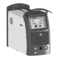
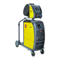
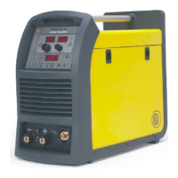
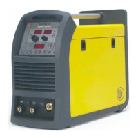
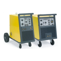
MULTI-FUNCTION INVERTER GENERATOR FOR MIG-MAG,
MMA, and TIG WELDING
The DIGITECH vision PULSE series of multi-function equip-
ments are characterised by cutting edge, attractive design
combined with latest generation inverter technology and digi-
tal welding control. Innovative, technologically advanced, ro-
bust, and easy to use, they can be used for very high quality
MIG-MAG and Pulse MIG welding for all materials and espe-
cially stainless steel and aluminium, reducing repeat work due
to spray to a minimum, using electrodes, and in TIG with “Lift”
type ignition, and they represent the best solution for all indus-
trial fields and all specialist welding purposes that call for high
precision and repeatable results. DIGITECH vision PULSE
equipments, fitted with an innovative synergic digital control,
colour display, and the extraordinary VISION-ARC meet the
needs of those that wish to combine synergy with complete
control of all welding parameters.
These are systems open to the future evolution of technology -
the control software can be kept up to date with the latest ver-
sions with the help of a personal computer.
Operating features
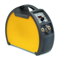
The main feature of the welding unit DIGITECH vision PULSE
3200 are:
• Metallic main structure with shockproof plastic front frames.
• Controls protected by a visor.
•
Exceptional characteristics for MIG-MAG, MMA, and TIG
welding with “Lift” type ignition.
•
Synergic digital control (DH) of all welding parameters, dis-
played via the innovative colour display, also featuring the
following functions:
-
Allows less expert operators to regulate all welding param-
eters in a user-friendly way and extremely easily, choos-
ing the type of program on the basis of the material, wire
diameter, and gas used.
- Innovative “VISION ARC” software for controlling all weld-
ing parameters.
-
With the special MIG torches you can adjust the welding
parameters at a distance straight from the torch.
- BURN BACK control. At the end of each weld, in any con-
dition and with any material, the digital control ensures a
perfect wire cut, prevents the typical “wire globule” from
forming and ensures correct arc restriking.
-
WSC Wire start control. This arc striking control device pre-
vents wire from sticking to the workpiece or torch nozzle
and ensures precise and smooth arc striking, particularly
when welding aluminium.
-
Welding parameters that are controlled digitally by a micro-
processor, are monitored and modified in just a few sec-
Introduction 2
Description 2
Operating features 2
Technical data 3
Usage limits (IEC 60974-1) 3
How to lift up the system 3
Opening the packaging 3
Installation and connections 3
Connection to the electrical supply 4
Loading wire 4
Assembly of drive rollers 5
Usage norms 5
MIG-MAG / PULSE MIG / DOUBLE PULSE MIG
Welding 5
Spot welding 5
Interval welding 6
Aluminium welding 6
Electrode welding (MMA) 6
TIG welding with “Lift” 7
Maintenance 7
Optional 7
The pointing out of any difficulties
and their elimination 8
Replacing the digital interface PCB 8
Simple automation 8
Meaning of graphic symbols on machine 9