32
WELDING MODE SELECTION LED
The LED unit indicates the welding mode saved in the JOB selected, which is coherent with
the VISION S
CREEN.
PARAMETER DISPLAY S
CREEN - V
Displays the JOB number also selected in the SEQUENCES or the value for the parameter
indicated by the PARAMETER SELECTION LED - V.
PARAMETER SELECTION LED - V
The LED unit indicates the welding parameter selected using the PARAMETER SELECTION K
EY
- V.
PARAMETER SELECTION K
EY - V Used to access displaying of the SPECIAL FUNCTIONS (Fx) saved in the JOB selected.
ENCODER K
NOB - V Used to scroll through the JOBS in the SEQUENCES as well, only if these are coherent. (*)
SPECIAL FUNCTIONS (F
X) KEY Used to access the SPECIAL FUNCTIONS (Fx) saved in the JOB selected.
(*) The JOBS included in the SEQUENCES as well as considered to be coherent when the last three figures (wire type,
gas, wire diameter) are equal. WHEN THIS IS THE CASE JOBS CAN BE CHANGED DURING WELDING WITHOUT INTER-
RUPTION.
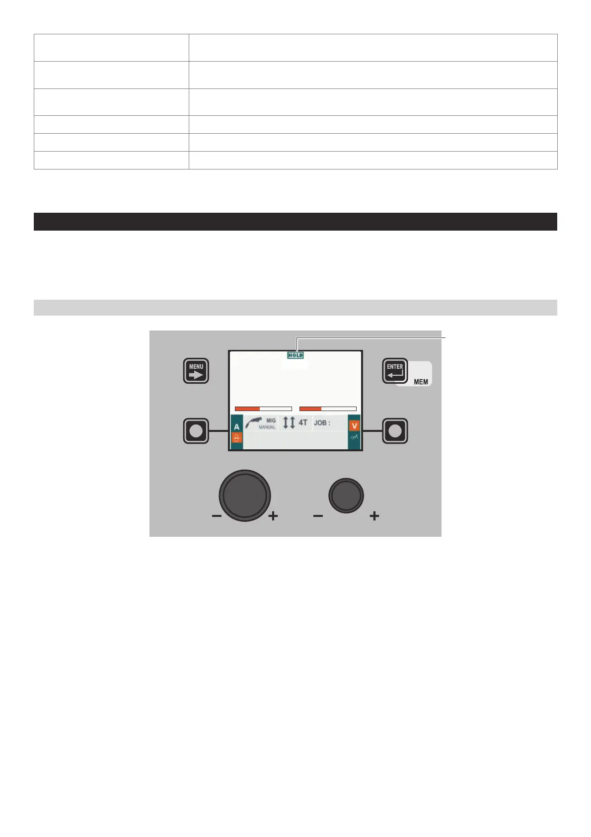
5 - HOLD JOB/SEQUENCES
When welding ends the fields in the display must show the same values that were displayed during welding, with the difference
that they are now values defined as HOLD. In this phase the VISION S
CREEN
shows the HOLD box highlighted, while on the HT5
panel the HOLD FUNCTION LED flashes until the end of the HOLD Function. If the HOLD Function is Interrupted via a panel (e.g. DH),
it will also be interrupted automatically on the other (HT5) and vice-versa.
WARNING: All the parameters saved within a JOB (including SPECIAL FUNCTIONS (Fx)) can be viewed but not edited!
“DH” / “VS” CONTROL PANEL
m/min V
11.1 33.3
013
HOLD