34
Error condition
WARNING: Under normal conditions of use it is not possible to open the “ERROR LOG Menu” display since the alarm message
appears instantaneously on the VISION S
CREEN as soon as the problem arises on the welding plant. At this stage it is not possi-
ble to weld!
As soon as the error message appears:
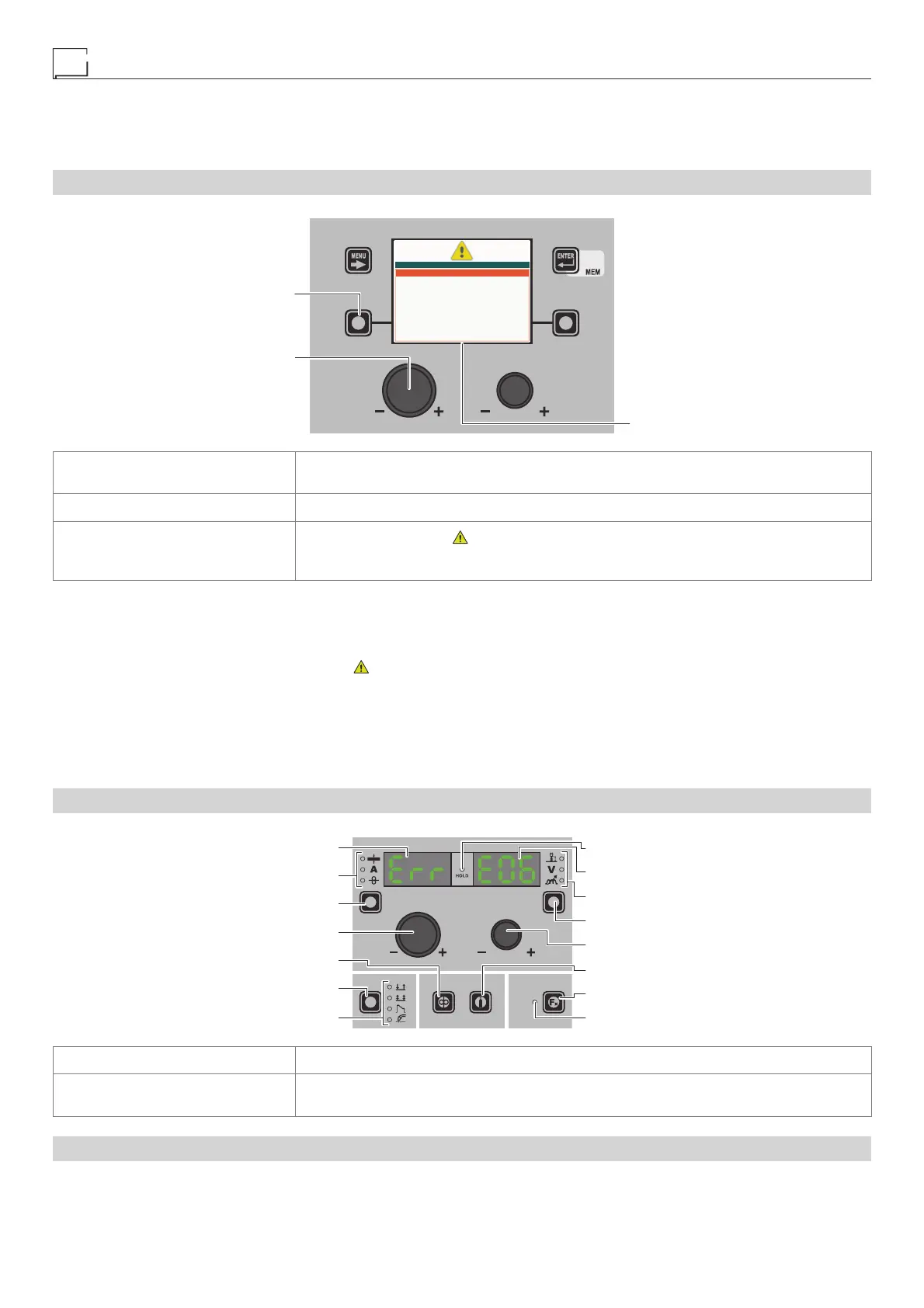
“DH” / “VS” CONTROL PANEL
ENCODER KNOB - SX
VISION SCREEN
SX KEY
ERRORS 1
E0.6 WATER COOLER MISSING
SX KEY
If held down for a period of about 5 consecutive seconds it takes the VISION SCREEN to the
SETUP Menu.
ENCODER K
NOB - SX Used to scroll the alarms activated.
VISION S
CREEN
Shows the alarm signal ( ), number of the errors that have occurred (e.g. ERRORS 1) and
an indication of what happened (e.g. E.06 WATER COOLER MISSING) of the welding ma-
chine.
In the case of an Automatically reset error once the alarm condition has ended (reinstatement completed correctly), the weld-
ing plant is once again ready and the operator can recommence welding! The alarm state disappears and the VISION S
CREEN re-
turns to precisely the same point at which it was operating previously.
PLEASE NOTE: After resetting has been completed, during normal operation of the machine, the VISION S
CREEN will still show the
error signal to inform the operator of the event ( ), but this can be removed visually from the display by simply pushing the MENU
KEY. WARNING: This only removes the visual error indication but not the history of what happened!
In the case of NON automatically reset errors, to remove the alarm status and reinstate correct operation of the machine, the
welding plant must be switched off.
When it is switched on again, the machine will be working again and the operator can weld again!
PLEASE NOTE: If, when switching on, the error status presents itself again, immediately contact’s Technical Assis-
tance Department.
“HT5” CONTROL PANEL (not used with DH 32 and VS 32)
WELDING MODE SELECTION LED
WELDING MODE SELECTION K
EY
WIRE KEY
ENCODER KNOB - A
PARAMETER SELECTION K
EY - A
PARAMETER SELECTION LED - A
PARAMETER DISPLAY S
CREEN - A
SPECIAL FUNCTIONS (FX) LED
SPECIAL FUNCTIONS (FX) KEY
GAS KEY
ENCODER KNOB - V
PARAMETER SELECTION KEY - V
PARAMETER SELECTION LED - V
PARAMETER DISPLAY SCREEN - V
HOLD Function LED
PARAMETER DISPLAY SCREEN - A Displays the error message (e.g. Err.).
PARAMETER DISPLAY S
CREEN - V
Shows the alarm code (e.g. E0.6) of in succession, the codes for the alarms in succession if
there are a number of errors.
In the case of an Automatically reset error once the alarm condition has ended (reinstatement completed correctly), the weld-
ing plant is once again ready and the operator can recommence welding! The alarm state disappears and the VISION S
CREEN re-
turns to precisely the same point at which it was operating previously.