4
This system is cooled by means of the forced circulation of air,
and must therefore be placed in such a way that the air may
be easily sucked in and expelled through the apertures made
in the frame.
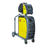
Assemble the system in the following way:
• Assemble the trolley.
• Fixing the cooling unit to the trolley.
•
Fixing of the welding machine to the trolley and the cooling
unit (electrical and plumbing connections).
• Connect up the welder to the mains.
•
Connect up the wire-feeder/generator interconnection cable.
• Connect up the welding cables.
Instructions for fitting the individual components / optional ex-
tras are contained in the relevant packaging.
Connection to the electrical supply
Connection of the machine to the user line (electrical cur-
rent) must be performed by qualified personnel.
Before connecting the welding machine to the mains pow-
er supply, make sure that rated voltage and frequency cor-
respond to those provided by the mains power supply and
that the welding machine’s power switch is turned to “O”.
Use the welder’s own plug to connect it up to the main pow-
er supply. Proceed as follows if you have to replace the plug:
•
3 conducting wires are needed for connecting the machine
to the supply.
•
The fourth, which is YELLOW GREEN in colour is used for
making the “GROUND” connection.
Before connecting the welding machine to the mains pow-
er supply, make sure that rated voltage and frequency cor-
respond to those provided by the mains power supply and
that the welding machine’s power switch is turned to “O”.
Table 2 shows the capacity values that are recommended for
fuses in the line with delays.
Table 2
Model
DIGITECH vision
PULSE 3200
MIG-MAG welding
Input power @ I
2
Max kVA 18,8
Delayed fuse (I
2
@ 60%) A 25
Duty cycle @ 40% (40°C) A 320
Mains cable
Length
Section
m
mm
2
4
4 × 2,5
Ground cable mm
2
50
NOTE: Any extensions to the power cable must be of a suita-
ble diameter, and absolutely not of a smaller diameter than the
special cable supplied with the machine.
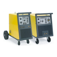
Loading wire
•
Fit the reel (diam. 300 mm) on the support so that the wire
unrolls clockwise, and center the projecting reference on the
support with the relative hold on the reel.
•
Thread the end of the wire into the back guide (Pos. 1, Fig. A)
on the drawing mechanism.
•
Lift up the idle rolls (Pos. 4, Fig. A) releasing the roll pres-
sure device (Pos. 2, Fig. A). Make sure that the drive rolls
(Pos. 7, Fig. A) have the diameter corresponding to the wire
being used stamped on the outside.
• Insert the wire into the central wire guide and the wire guide
on the centralised connection (Pos. 5, Fig. A) by a few cen-
timetres. Lower the idle roller holder arms, making sure that
the wire slots into the hollow in the motor’s roller. If neces-
sary, adjust the pressure between the rollers by turning the
6
5
2
3 4 4 3
2
1
6
FIG. A
6
1
5
4
9
7
8
2
3
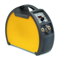
FIG. B