Do you have a question about the Chamberlain CAPXL and is the answer not in the manual?
Explains safety symbols and signal words used in the manual to alert users to potential hazards.
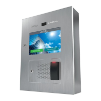
Provides an overview of CAPXL/CAPXLV as cloud-based access control solutions for residential communities.
Details the components and connections of the Power/Internet board within the CAPXL/CAPXLV system.
Explains the inputs/outputs on the Door Boards that control up to 4 access points.
Provides the physical dimensions of the CAPXL/CAPXLV unit, including front, side, and bottom views.
Lists the technical specifications of the CAPXL/CAPXLV, covering capacity, voltage, temperature, and more.
Details wire types and maximum run distances required for various connections during installation.
Outlines necessary internet speeds, Wi-Fi communication protocols, and security compatibility.
Guides on creating and setting up a myQ® Business™ account for system functionality.
Details network configuration settings required for internet connectivity of the CAPXL/CAPXLV.
Explains requirements for phone service, particularly for video calls using a SIP provider.
Instructions on how to safely remove knockouts from the CAPXL/CAPXLV housing for wiring.
Steps for securely mounting the CAPXL/CAPXLV unit to a surface or pedestal.
Guidance on installing the Security+ 2.0® radio antenna and Wi-Fi® antennas.
Details the importance and procedure for installing an earth ground connection for the unit.
Instructions for connecting the dedicated 120 Vac power supply to the CAPXL/CAPXLV.
Steps for connecting the device to the internet via wired Ethernet or Wi-Fi.
How to check and confirm network and system configurations in Admin Mode.
Example wiring setup for wired gate access control to Door 1, 2, 3, or 4.
Steps for wirelessly pairing CAPXL/CAPXLV with LiftMaster gate operators.
Example wiring setup for door access control configurations.
Instructions for mounting and wiring an LMMC-MINI reader to the CAPXL/CAPXLV faceplate.
Detailed wiring diagram for the LiftMaster LMSC1000 RFID Reader.
Explains Wiegand output data transmission capabilities for access events.
Instructions for installing the postal lock switch onto the CAPXL/CAPXLV.
Guide for upgrading the CAPXL unit with the CAPXLCAM USB camera.
Tasks to perform before installing the CAPXLCAM, including firmware and settings checks.
Step-by-step guide for physically installing the CAPXLCAM camera assembly.
Explains how to configure the Auto Call feature using a loop detector.
Illustrates the complete system wiring connections for the CAPXL/CAPXLV.
Details FCC compliance statements, including limits for Class B digital devices.
Mentions compliance requirements with the Canadian Electrical Code.
States restrictions on document usage, copyright, and liability.
Lists UL ratings for access control unit endurance, line security, and attack resistance.
Outlines the terms and conditions of the product's limited two-year warranty.
| Category | IP Access Controllers |
|---|---|
| Manufacturer | Chamberlain |
| Operating Voltage | 12-24V DC |
| Connectivity | Ethernet |
| Inputs | 4 supervised inputs |
| Communication Protocol | TCP/IP |
| Max Users | 10, 000 |
| Event Log | 50, 000 events |
| Weight | 200g |
| Supported Readers | Wiegand |
| Relay Outputs | 2 |
| Operating Temperature | -20°C to 60°C |
| Outputs | 2 relay outputs |