17
1
Connect Internet
The CAPXL / CAPXLV can connect to the Internet with a wired connection or with Wi-Fi
®
(wireless). See page 10 for Internet requirements. Make sure you are in the Admin Mode before
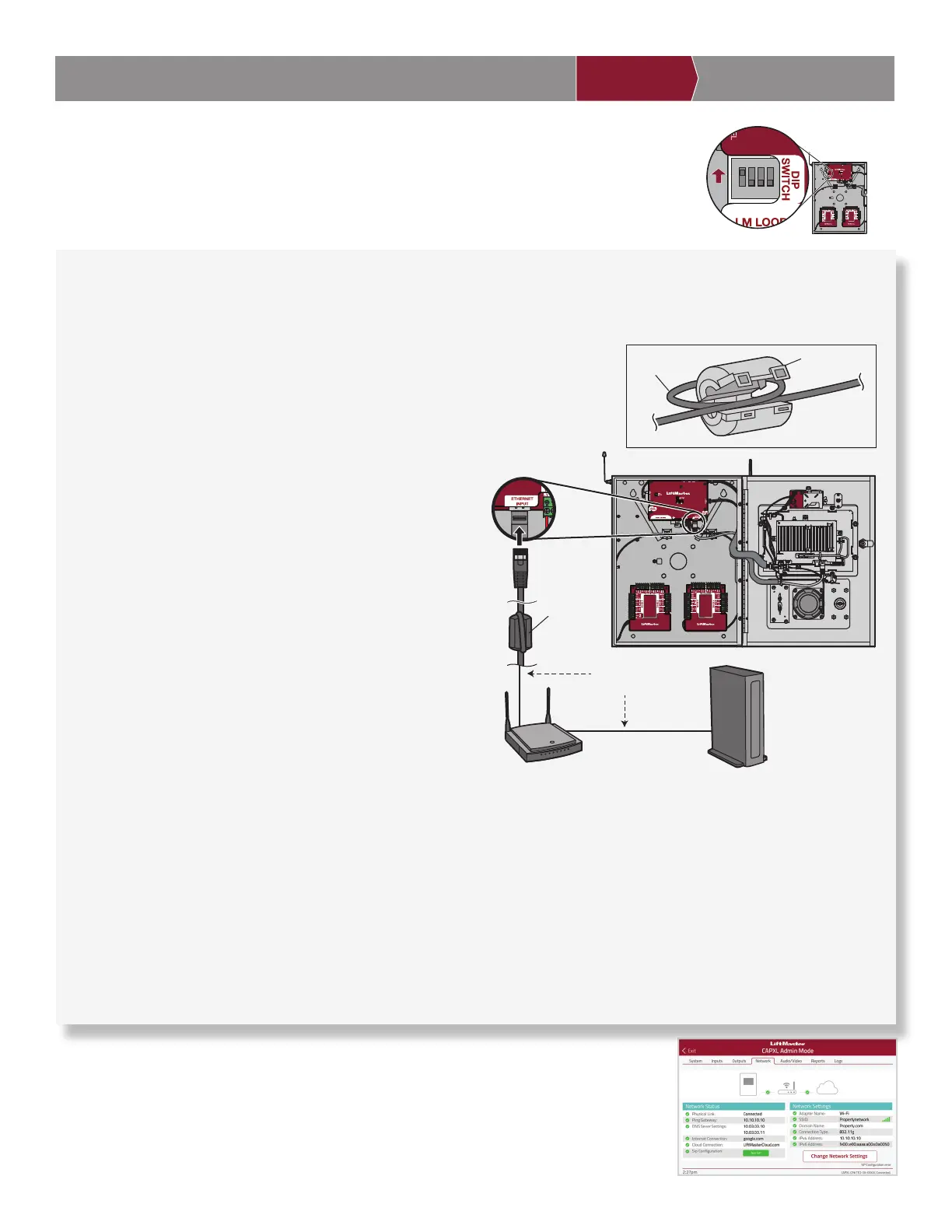
you connect to the Internet. If you are not in Admin Mode, fl ip dipswitch #1 to the ON position
on the Power/Internet board, press the Network tab on the CAPXL / CAPXLV display, and press
the “Change Network Settings” button. Follow the instructions according to your application.
INTRODUCTION PRE-INSTALL NETWORKINSTALL ACCESS CONTROL
On the display, select each tab in Admin Mode to validate setup (network,
inputs, outputs, etc.). Once you have validated the setup, exit Admin Mode.
Validate Setup
2
OPTION 1 Wired Connection
The Local Area Network (LAN) port is a 10/100/1000 Ethernet interface with an RJ45 jack for connecting the CAPXL / CAPXLV to a hub, switch,
or router in order for it to gain connectivity to the Internet. Use a straight, (i.e., non-crossover) Cat5, Cat5e, or Cat6 cable to connect to a local
hub, switch or router. This type of cable is referred to as an Ethernet cable in this manual.
1. Open the Ferrite Core.
2. Loop the Input Ethernet cable around itself one time, creating a loop large enough to fi t over
the length of the Ferrite Core. Locate the cable loop near the intended electrical knock-out.
3. Place looped section of Input Ethernet cable over one side of the
open Ferrite Core.
4. Close the Ferrite Core securely and plug the Input Ethernet cable
into the Power/Internet board.
5. Connect an Ethernet cable from the hub, switch, or router to the
LAN port on the Power/Internet Board. When connected properly,
the green and amber LED on the Ethernet port of the control
board will light/fl icker (the control board is located on the back of
the CAPXL / CAPXLV display). If the green LED is not lit, check
the connections on the CAPXL / CAPXLV and the Ethernet hub.
6. On the display, select Wired Network if dynamic confi guration
(DHCP) is desired or select Manual Setup for a static IP address.
OPTION 2 Connect through Wi-Fi
®
(Wireless)
1. On the display select Wi-Fi
®
Network.
2. Select the network the CAPXL / CAPXLV will use.
3. Enter the password for the network.
4. Select Login.
Additional compatibility considerations:
• When checking signal strength in CAPXL / CAPXLV admin mode, we recommend at least two bars.
• If two bars are not available, relocate the router, the antenna or use accessory WFAEXT (Wi-Fi
®
Antenna Extension Kit – 15’) to
move the CAPXL / CAPXLV antenna higher up or to a location resulting in two or more bars.
• If using a Wi-Fi
®
signal strength tool or app, a continuous Wi-Fi
®
signal strength connection of at least -65 DBM (numbers closer
to zero are stronger strength) at the CAPXL / CAPXLV must be guaranteed to ensure an acceptable connection to the local network.
• Hidden network SSID’s are not supported. The network must be selectable from the CAPXL / CAPXLV display.
• Wi-Fi
®
networks requiring secondary authentication are not supported (E.g. Hotels and airport Wi-Fi
®
).
ON
LAN on
Power/Internet Board
Ferrite Core
Modem
Router/Switch
Ethernet Cable
(325 feet [99.1 m] maximum)
ON
Dipswitch #1 on the
Power/Internet board
Ferrite Core
Input Ethernet
Cable