12
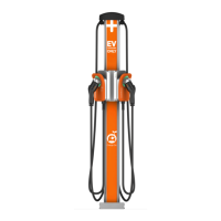
6. Hold the mounting template against the wall.
7. Align the lower mounting holes on the installation template
with the holes marked in the previous step.
8. Mark the top mounting hole from the installation template on
the wall.
9. Remove the template from the wall.
10. Drill the three mounting holes using a drill bit suitable for the
type of wall material.
• For wood stud mounting, drive one of the supplied 51 mm (2
in) lag screws into the top mounting hole, leaving a gap
between the screw head and the wall of 3 mm (1/8 in).
• For masonry or concrete mounting, drill the three mounting
holes by following the instructions for the wall anchors. Set
the three anchors. Insert a screw into the top mounting
anchor, leaving a gap between the screw head and the wall
of 3 mm (1/8 in) protruding.
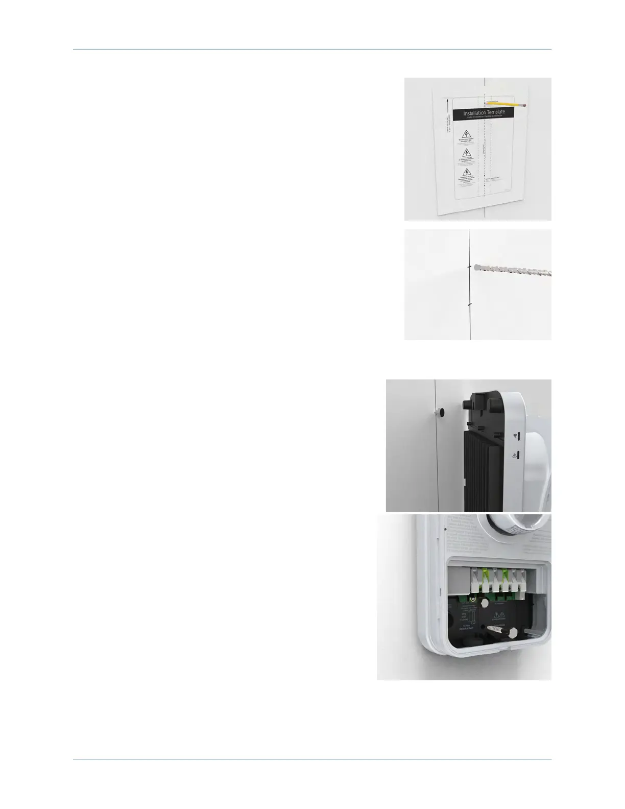
11. Hang the charging station on the protruding screw from the
notch on the back of the charging station.
12. Secure the station by inserting the remaining fasteners
into the mounting holes located in the stations terminal
block area.
• For wood mounting, use the two 51 mm (2 in) lag
screws provided.
• For masonry or concrete mounting, use the two
remaining masonry screws in the anchors.
Proceed to Section 9 to Review the Wiring Diagram.