Installation Edge MAXX
2-10
Communications Cable Connection
(Option)
If the unit was shipped with the optional
communications cable, locate it at the
right rear of the machine (Figure 2-15,
A). Uncoil the cable and connect to the
communications port on the right front of
the ironer (Figure 2-14, B).
Interconnected Stop Circuit Cable
Connections (Option)
If the unit was shipped with the optional
Interconnected Stop Circuit, it also will be
located at the right rear of the unit (Figure
2-15, B).
NOTE: Save this plug. It will be
needed if the feeder unit is ever
run as a single machine.
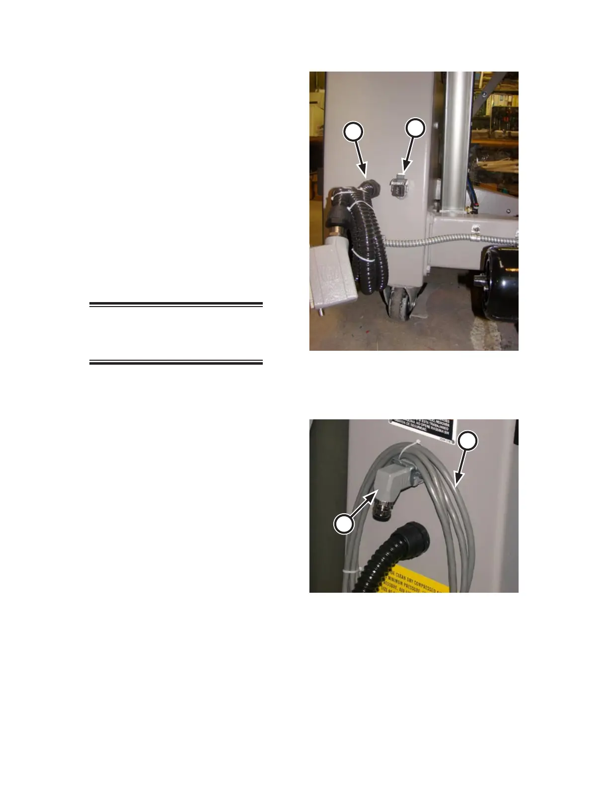
Remove the feedback plug from the stop
circuit connector (Figure 2-16, A).
Uncoil the stop circuit cable (Figure
2-16, B) and attach it to the stop circuit
connector. Pull the latch to secure the
connection.
Remove the feedback plug from the ironer
behind the spreader/feeder (Figure 2-14,
C) and connect the stop circuit cable to
its plug. Pull the latch the secure the con
-
nection.
1.
1.
2.
3.
4.
Figure 2-16: Interconnected Stop Circuit plug at the
left rear of the spreader/feeder.
A
B
Figure 2-15: The communication cable is at the left
rear of the spreader/feeder.
A
B