Edge MAXX Installation
2-11
Standard Electrical Wiring
WARNING
Only a qualified electrician
should make the electrical
connections to the unit.
Improper installation could
result in serious injury.
Required Tools
screwdriver, 3/16” Allen wrench
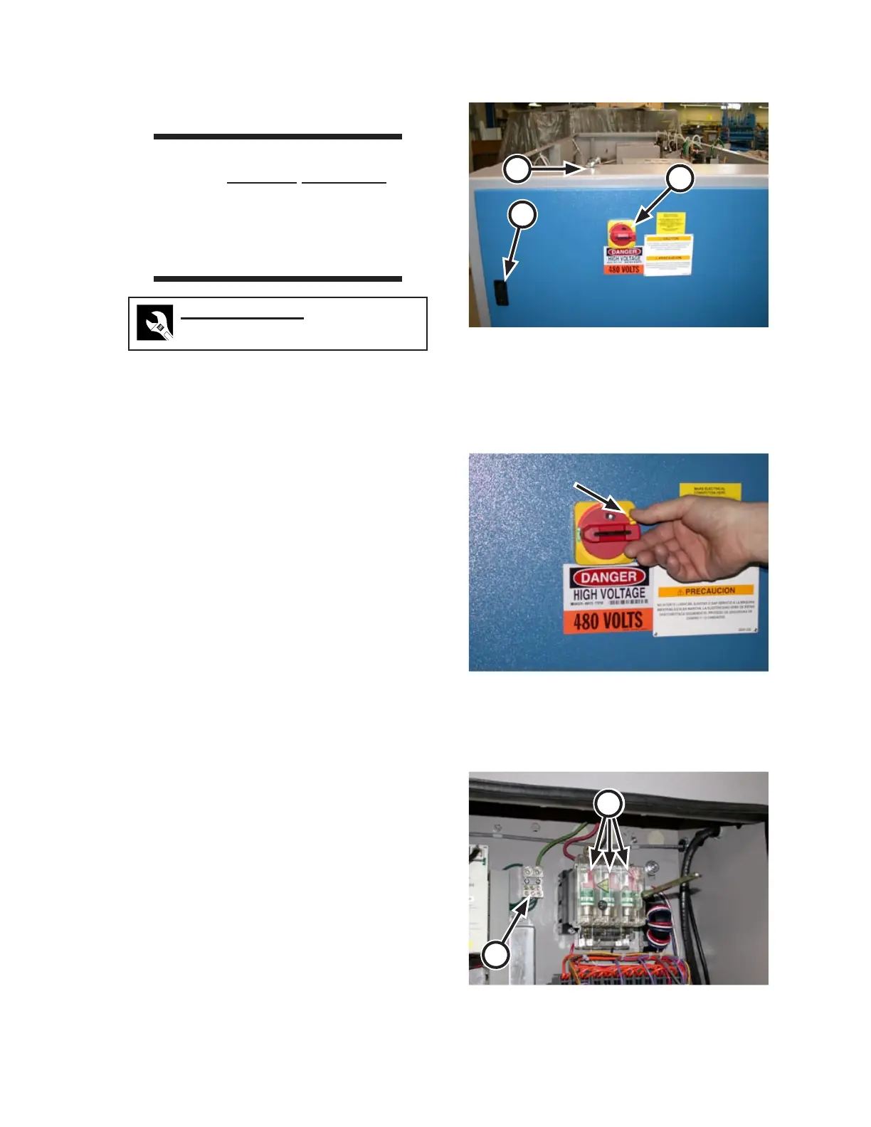
The main disconnect is located on the right
endframe door. Turn it to the OFF position
(Figure 2-17, A).
Open the upper (Figure 2-17, B) and lower
right endframe door latches.
Rotate and hold the yellow lever while
holding the main disconnect switch in the
OFF position (Figure 2-18), then open the
right endframe door.
Bring the supply lines to the top of the
right endframe (Figure 2-17, C). Use three
wires for the power supply. A green fourth
wire for ground is required.
Extend the lines through conduit or green-
field. If it will be necessary to move the
unit, leave plenty of slack in the greenfield
for this purpose.
Pull the external wiring through the hole
in the top of the electrical box and secure
the conduit or greenfield to the box. Fol-
low local codes at all times.
Connect the three incoming power wires to
the fused terminals of the main disconnect
switch (Figure 2-19, A).
Connect the ground wire to the ground
-
ing lug (Figure 2-19, B) using the Allen
wrench.
1.
2.
3.
4.
5.
6.
7.
8.
Figure 2-17: Open the right endframe door for
standard electrical wiring.
A
B
C
Figure 2-19: The electrical supply is connected at
the top of the main disconnect switch.
A
B
A
A
Figure 2-18: Rotate the yellow lever and hold against
the red main disconnect switch to open
or close the main electrical box.