Edge Maxx Operating Principles
5-3
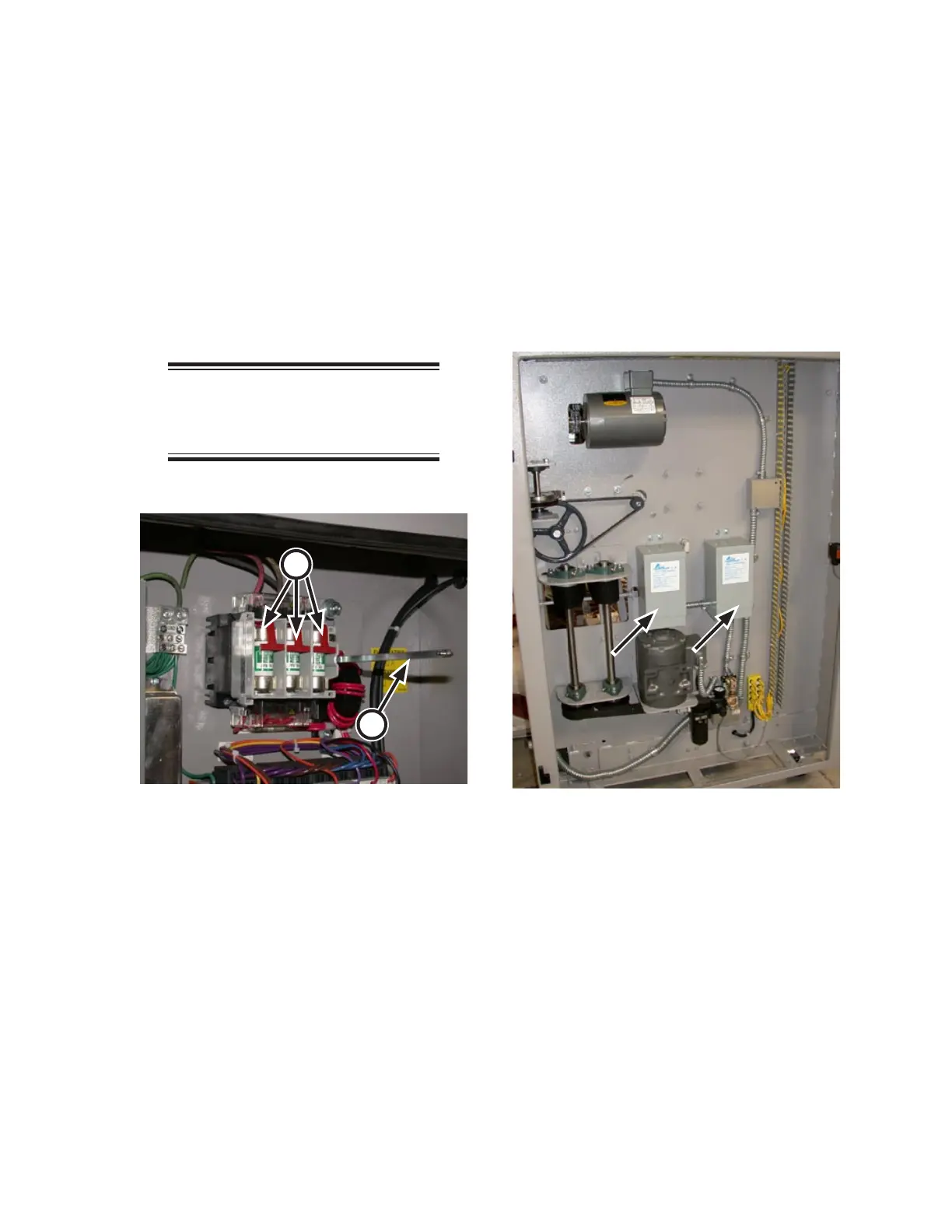
Disconnect Switch and Fuses
The unit comes equipped with a disconnect
switch (DDS). This switch (Figure 5-1, A)
is located in the electrical panel in the right
endframe.
Included as a part of the disconnect switch
are a set of fuses (B), which will isolate the unit
from the mains if necessary. See the schematics
for the rating of these fuses, which is dependent
on line voltage.
NOTE: The power supplied to the
unit must match the requirements
listed on the nameplate.
Step-Down Transformers
If the unit is installed in a property with line
voltage higher than 240 VAC, transformers T1
and T2 are provided (Figure 5-2) in the left
endframe. These adjust the voltage to 240 VAC,
which is used throughout the unit.
Figure 5-1: The disconnect switch (A) and fuses
(B) provide isolation from the mains.
A
B
Figure 5-2: Step-down transformers are mounted
in the left endframe.
 Loading...