Operating Principles Edge Maxx
5-6
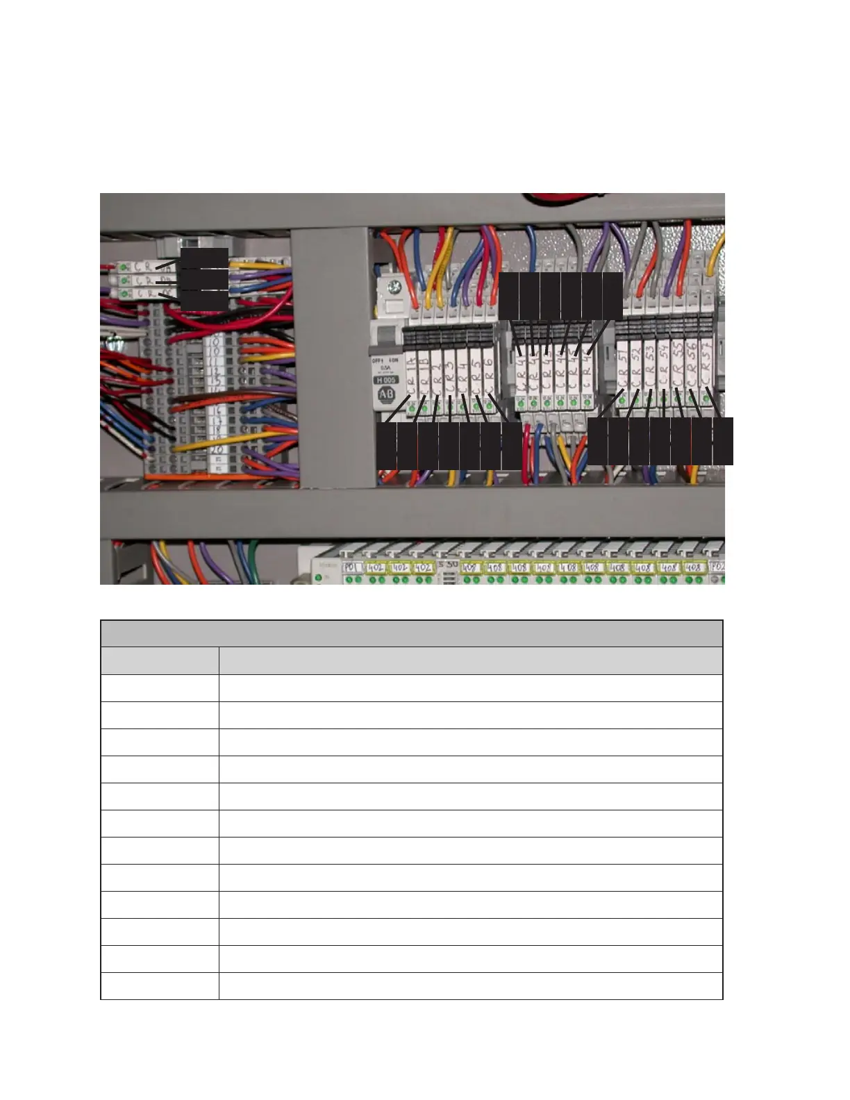
Additional Electrical Panel Control
Relays
The function of these relays is described in
the table below.
ADDITIONAL ELECTRICAL PANEL CONTROL RELAYS
Schematic Description
CR0 (A/B/C) Control Relays - Start Circuit
CR1 (A/B) Control Relays - Control Power Latch
CR2 Control Relay - E-Stops
CR3 Control Relay - Inverter Fault Contacts
CR4 Control Relay - Motor Protectors
CR5 Control Relay - Run
CR6 Control Relay - Run Latch
CR41-CR42 Control Relays - Left Inlet Touch Sensors
CR43-CR44 Control Relays - Right Inlet Touch Sensors
CR45 Control Relay - Crossbeam Sensor
CR46 Control Relay - Inlet Touch/Crossbeam Safety Circuit
CR51 to CR57 Control Relays - Motor1 thru Motor7 Thermostats
Figure 5-4: Additional control relays in the electrical panel.
CR0A
CR0C
CR0B
CR1A
CR1B
CR2
CR3
CR4
CR5
CR6
CR41
CR42
CR43
CR44
CR45
CR46
CR51
CR52
CR52
CR54
CR55
CR56
CR67
 Loading...