[DB600] General Instruction Manual
- 18 -
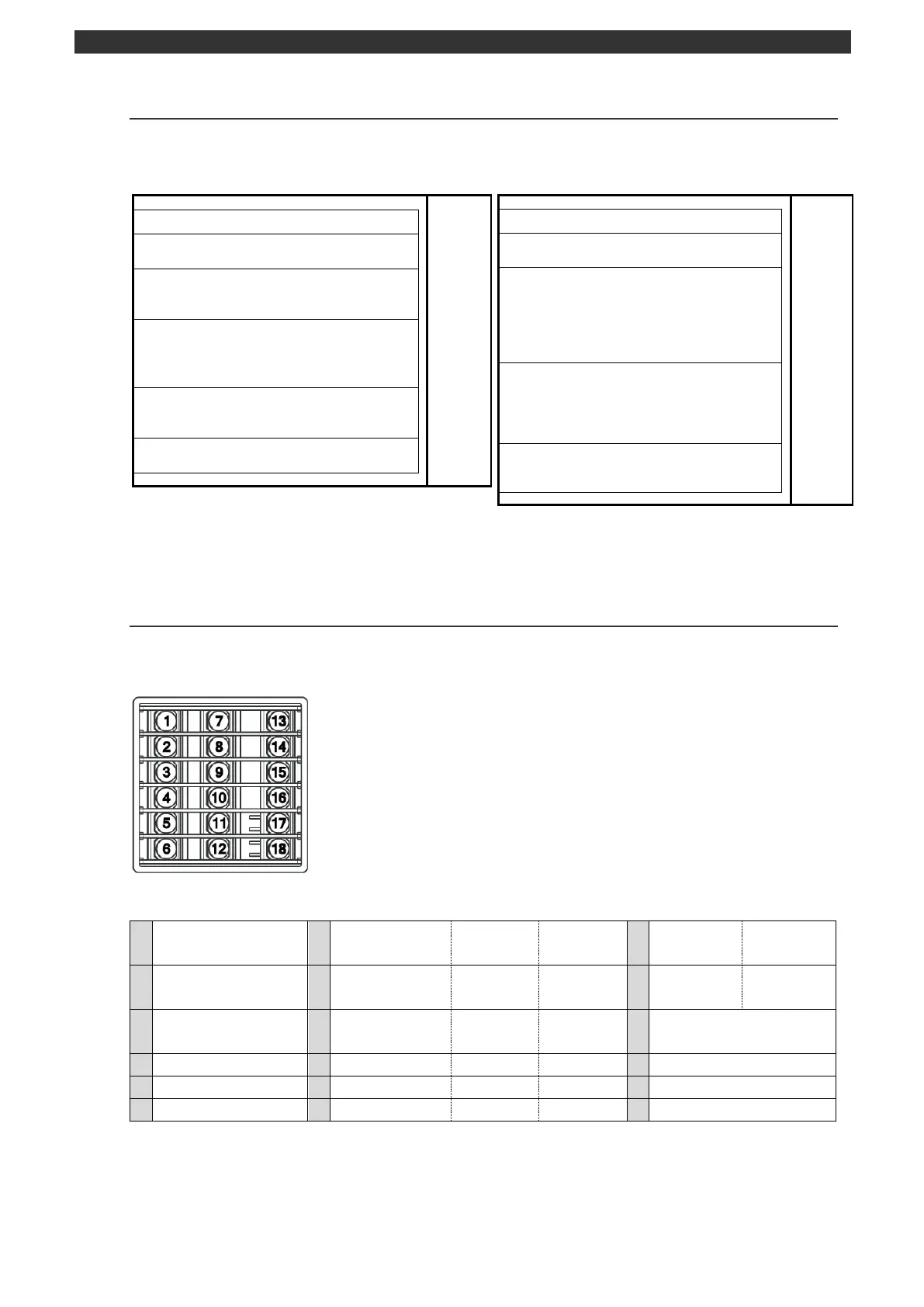
2-3-2
Insulation block
In the chart below, circuit divided by the lines are insulated from other circuits.
Measuring input terminals
Remote input terminals R/L (analog) DI terminals
Control output 1/2 terminals
(current output type/SSR drive pulse output type/
voltage output type)
Control output 1/2 terminals (ON-OFF pulse output
type)
Event output 1/2 (mechanical relay output)
terminals
Communications terminals R/L (digital) DI
terminal
External signal input (DI1 to 5) terminals
Event output 5 to 9 (open corrector output)
terminals
*For “24V AC/DC”, power terminals are at secondary side.
*Between control output 1/2 (ON-OFF pulse output type) and event
output 1/2 (mechanical relay output) is isolated.
Measuring input terminals CT input terminals
Remote input terminals R/L (analog) DI terminals
External signal input (DI6/7) terminals
Control output 1/2 terminals
(current output type/SSR drive pulse output type/
voltage output type)
ON-OFF servo (feedback input) terminals
Transmission output (4 to 20mA DC/0 to 1V DC/0
to 10V DC)
Control output 1/2 terminals (ON-OFF pulse
output type)
Event output 1 to 4 (mechanical relay output)
terminals
ON-OFF servo (relay output) terminal
Communications terminals R/L (digital) DI terminal
External signal input (DI1 to 5) terminals
Event output 5 to 9 (open corrector output )
*For “24V AC/DC”, power terminals are at secondary side.
*Between control output 1/2 (ON-OFF pulse output type) and event
output 1 to4 (mechanical relay output) is isolated.
2-3-3
Terminal number and functionality
Depending on the instrument model, there are places where terminal screw is not provided.
DB630
Terminal layout