Chore-Tronics® 3 Control Control Installation
MT2398C
109
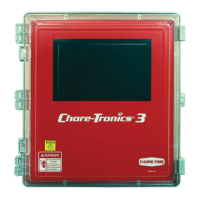
Analog Expansion Boards- Each Analog Expansion Board (AI.4 board) adds 4 additional Analog
Inputs to the Chore-Tronics
®
3 Control. There is a Blue Jumper located above each Analog Input (Item
2, Figure 37). This Blue Jumper needs to be set in the "R" position if a resistive Analog Input
(Temperature Sensors and Potentiometers) is connected. The Blue Jumper should be set to "U" if a voltage
Analog Input (Static Pressure Sensor, Relative Humidity Sensor) is connected. There is a +24 Vdc output
available if needed. When assigning the Input in the Setup-General screen make sure that the number of
the Analog Expansion Board is correct along with the number of the Analog Input itself (1-4). It is highly
recommended that the name of the Input as well as its assigned location be written on the Input Decal
located on the Cover Plate of the Main Box and also recorded in the Input Assignments Diagram on
page 137.
Item Description
1 Analog Expansion Board
2Blue Jumper
3 +24 Vdc Output
3
2
1
Figure 37. Analog Expansion Board
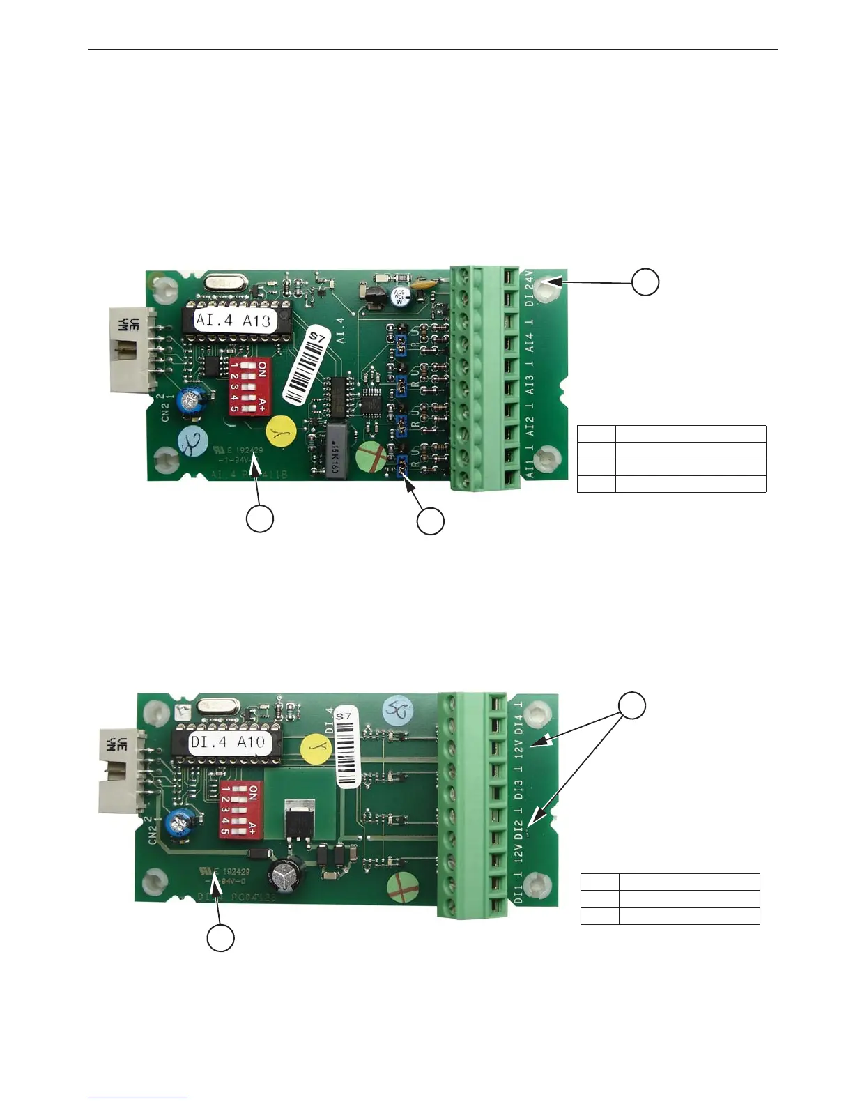
Digital Expansion Boards- Each Digital Expansion Board (DI.4 board) adds 4 additional digital inputs
to the Chore-Tronics
®
3 Control. There are multiple +12 Vdc outputs available if needed (Item 2, Figure
38). When assigning the Input in the Setup-General screen make sure that the number of the Digital
Expansion Board is correct along with the number of the digital input itself. It is highly recommended that
the name of the Input as well as its assigned location be written on the Input decal located on the cover
plate of the main box and also recorded in the Input Assignment Diagram on page 137.
2
Item Description
1 Analog Expansion Board
2 +24 Vdc Output
1
Figure 38. Digital Expansion Board