Electrical Safety Analyzer 19032 User’s Manual
4-28
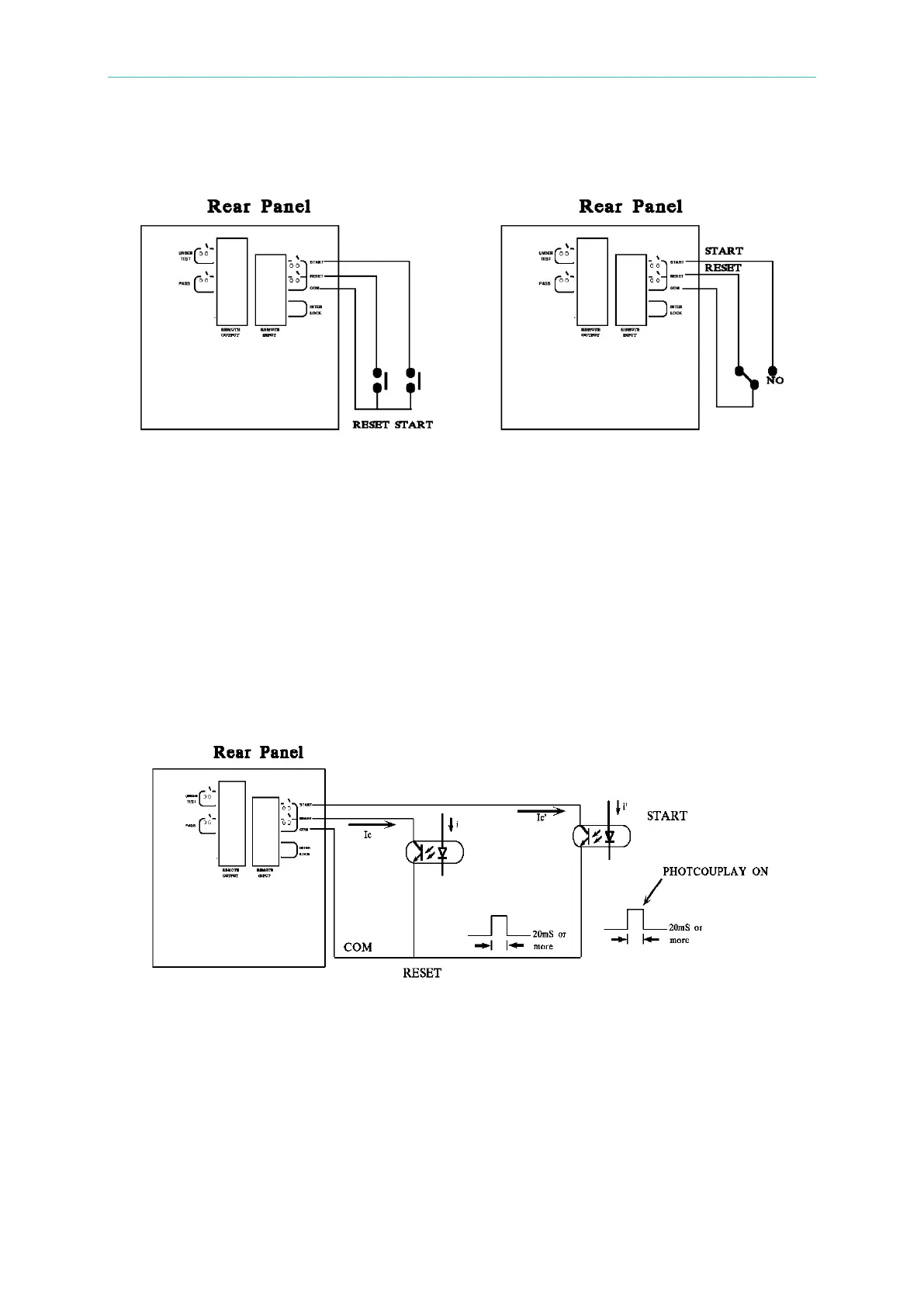
1. Remote control can be by individual START and STOP signals or by a continuous signal,
as shown in Figures 4-12 and 13.
Figure 4-12 – Single Control of START and STOP Figure 4-13 – Continuous Control of
STOP
2. As shown in Figure 4-13, the analyzer is under STOP status (the NC contact is
connected to STOP and the NO contact is connected to START.)
3. Logic components such as transistors, FETs, optocouplers, etc., can also be used for
control circuits, as shown in Figure 4-14.
4. The control signals should be within the following ranges:
(1) The HIGH signal voltage should between 4.5 and 5V.
(2) The LOW signal voltage should between 0 and 0.6V.
(3) The LOW signal current should be 2mA or less.
(4) The control signals should be active for at least 20mS.
Figure 4-14
5. The relay switch control shown in Figure 4-12 and the optocoupler control shown in
Figure 4-14 both provide contact closure. Avoid interference on the signal lines to prevent
unexpected system operation.
6. The REMOTE CONTROL pin diagram is shown in Figure 4-15. Use this pin diagram
when connecting external control signals.