Descriptions of Panel
4-5
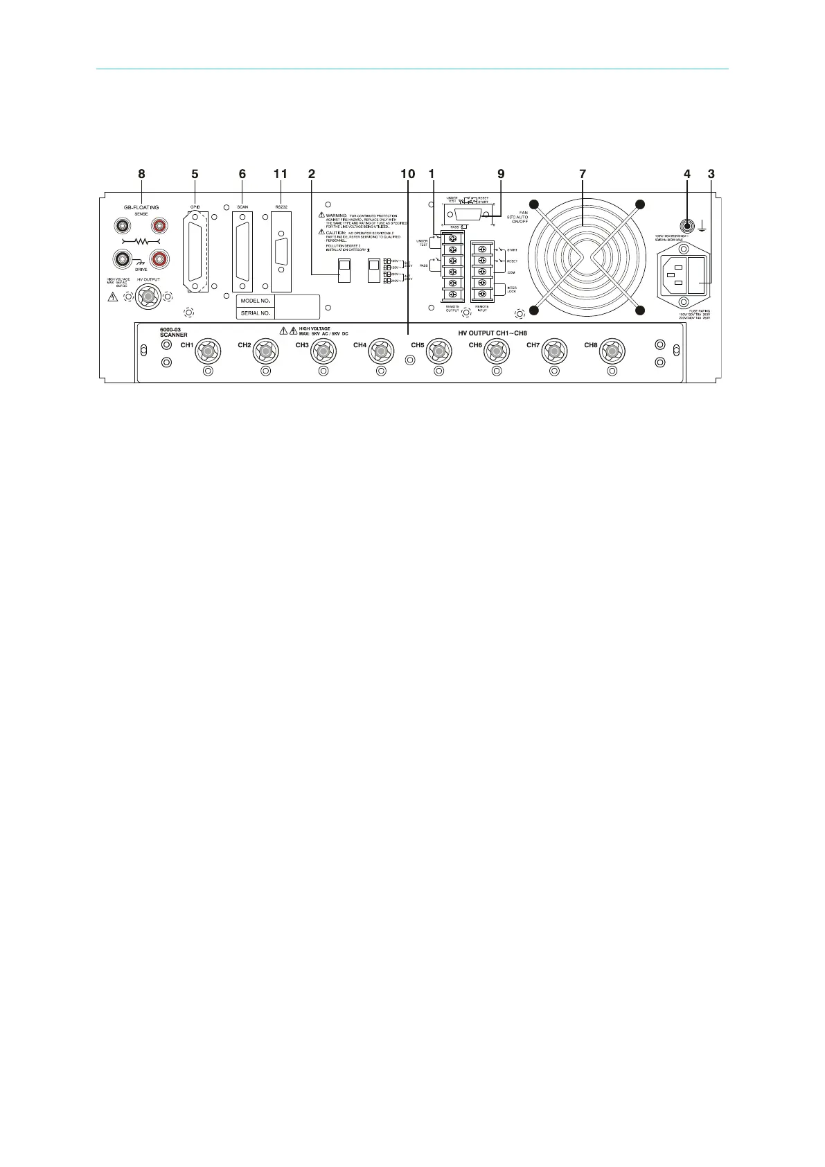
4.2 Rear Panel
Figure 4-2
(1) REMOTE I/O: The test result signal input/output terminals.
S TAR T: Start test signal input terminal.
RESET: Stop test signal input terminal.
INTER LOCK: HV can only be enabled when the two terminals are shorted together.
UNDER TEST: When the analyzer is running a test the output terminal relay contacts
will close. The relay contacts can support 115V AC, <0.3A. The test runs
until the RESET signal is received.
PASS: When the analyzer determines the DUT passed the test the output
terminal relay contacts will close. The relay contacts can support 115V
AC, <0.3A. The signal remains until the RESET signal is received.
(2) VOLTAGE SELECTOR Input Power Supply Range Switch
This test instrument supports the following input power voltage ranges:
a. 100V adaptable voltage range 90∼110V AC
b. 120V adaptable voltage range 100∼130V AC
c. 220V adaptable voltage range 200∼240V AC
d. 240V adaptable voltage range 220∼250V AC
If the voltage range is changed, be sure to change the fuse at the same time.
(3) AC LINE: AC power socket and fuse holder.
3-wire connection for AC power source. Fuse drawer: 8A 250V for
100-120 operation, 4A 250V for 220-240 operation.
(4) GND TERMINAL:
Safety GND terminal. Connect this terminal to earth ground. If this
terminal is not grounded, high voltage may exist on the cover, resulting
in a safety hazard.
(5) GPIB INTERFACE (Option):
This socket is for an optional GPIB interface (IEEE-488-1978). Refer to
“Chapter 5 – GPIB/RS-232 Operation Description (IEEE-488.2)” in this
manual for a detailed description.
(6) SCAN INTERFACE:
This interface connects with the 9030A Scanning Box (Option).