Electrical Safety Analyzer 19032 User’s Manual
4-30
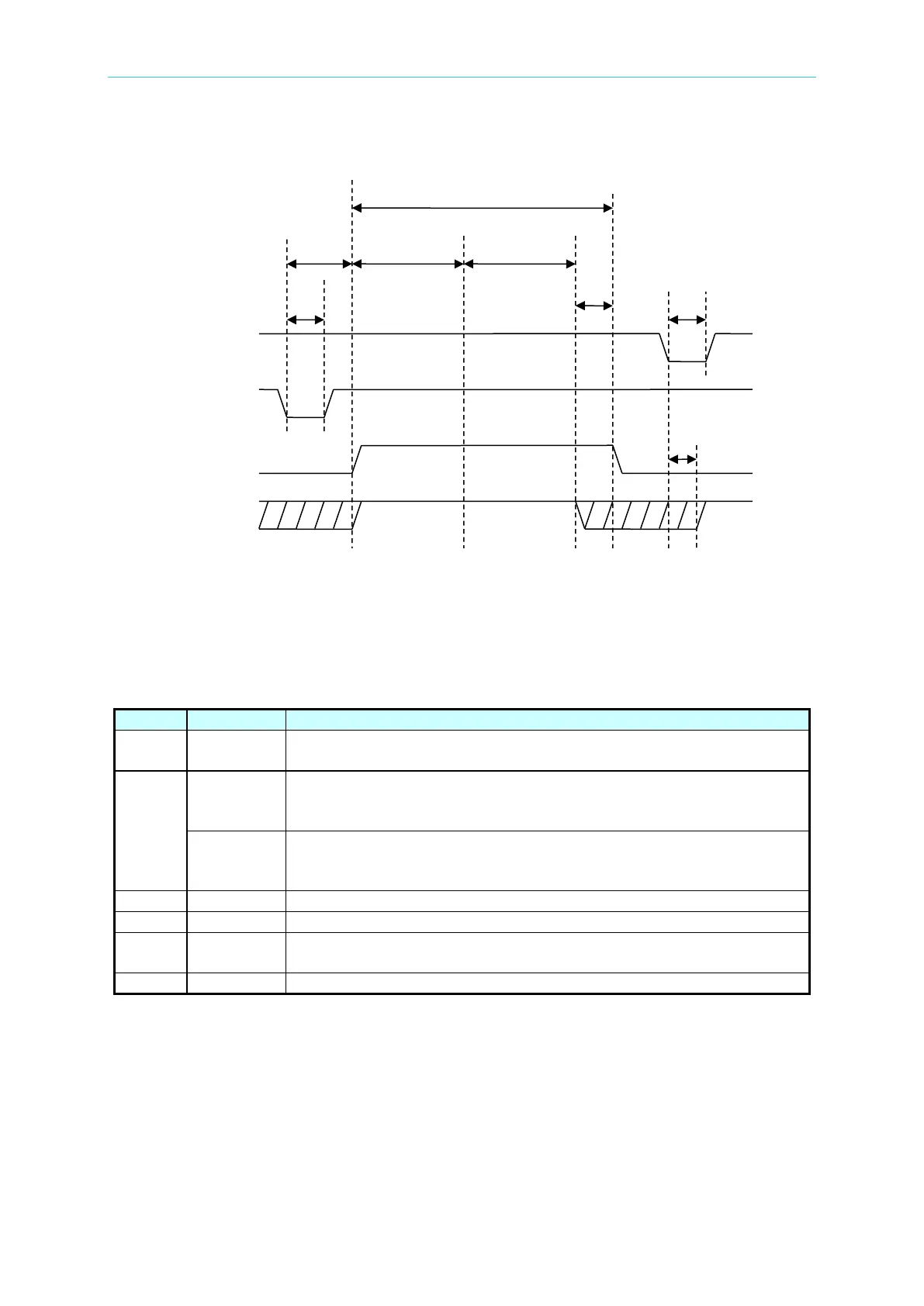
4.16 Timing Diagram
Timing diagram example for two test steps
T1 > 20mS
External trigger signals /START and /RESET need to be at least
20mS in duration.
T2
< 200mS
The time of external trigger signal /START to /UNDER TEST signal to
be cleared, it will be smaller than 200mS. The previous STEP test
result /PASS signal status has been cleared in advance.
< 300mS
The time of external trigger signal /START to /UNDER TEST signal to
be cleared, it will be smaller than 300mS. The previous STEP test
result /PASS signal status hasn’t been cleared in advance.
Test time of the test steps.
/PASS signal sent larger than 15mS, /UNDER TEST signal is end.
T5 -
The time used for testing. The signal is simultaneous with Danger
lamp on panel.
/RESET signal sent larger than 5mS, /PASS signal is ended.