Electrical Safety Analyzer 19032 User’s Manual
4-16
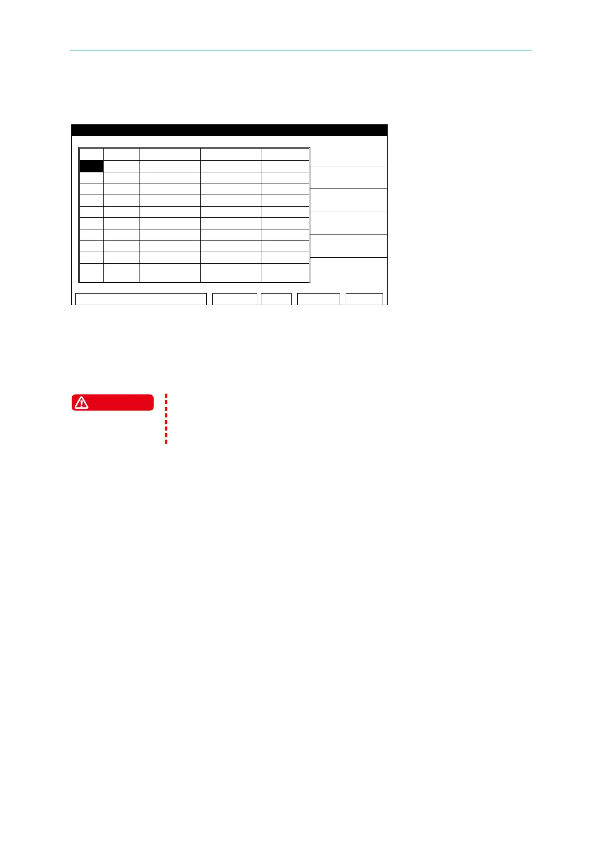
6. The output is stopped and the DUT can be changed. When the test cables are removed
from the DUT, the display will show:
Figure 4-10
7. There is no need to press the [START] key again after the first test. When the test cables
contact a new DUT, the 3 second countdown starts immediately.
8. After the 3 seconds have been counted down, the test process will begin automatically.
The START WAIT function is ACTIVE until the [STOP] button is pressed.
When START WAIT is ON, the test will start if contact is made with the
test leads. Use extreme caution when working near the analyzer or the
4.7 GB-Floating Board
4.7.1 Operating Notes
1. Before plugging in the AC power cable, ensure the fuse and voltage selector settings
match the power source being used and the power switch is OFF.
2. Before turning on power, read Safety Precautions in Chapter 3.
3. When the power is turned on, the analyzer will automatically perform a self-test. When
the LCD displays “Find GB-Float board”, it indicates self-test function is detected.
4.7.2 GB-Floating Description
1. When the selected test mode is WAC, WDC, or IR, the DRIVE- terminal on the rear panel
can be either grounded or floating.
2. When the selected test mode is GB or LC
(option), the DRIVE- terminal on the rear and
front panels are grounded terminals.
3. The rear panel is equipped with another set of HV OUTPUT (Channel 3). When the test
mode is WAC, WDC, or IR, capable of setting High or Low terminal or Disable. When the
test mode is LC
(option), HV OUTPUT only can be set as Low terminal or Disable.