Descriptions of Panel
4-17
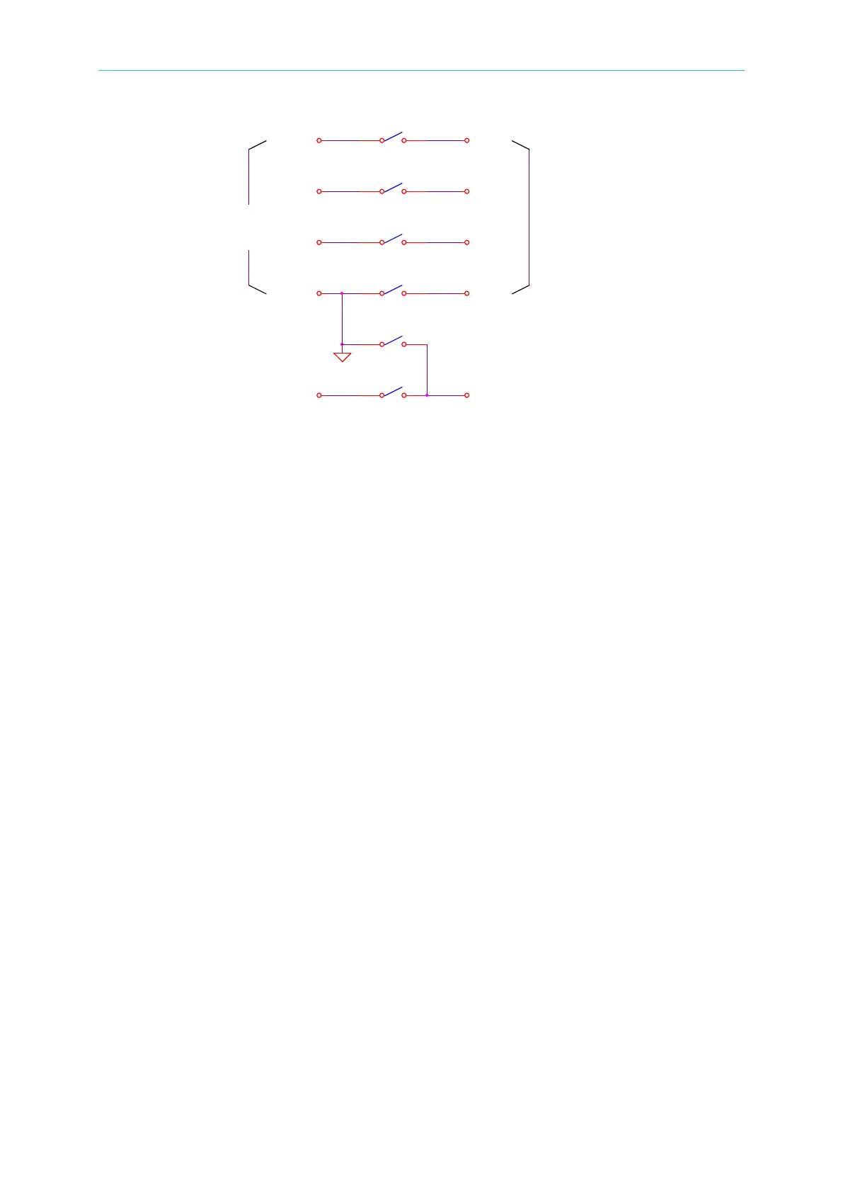
TEST 1: RL2, RL3, RL4, RL5 ---------- ON, RL1 --------- OFF
HV OUTPUT on rear panel is high voltage output.
TEST 2: RL1 ---------- ON, RL2, RL3, RL4, RL5 ---------- OFF
HV OUTPUT on rear panel is GND, DRV2_ on rear panel is Floating.
4.8 Program Setting
4.8.1 Operation Methods
1. When the title list displays “STEP SETTING”, press the [], [] keys to move the
highlighted cursor to the parameter to be set.
2. Press the numeric/character keys or Function Keys to set the parameter data.
3. Press [ENTER] to confirm or press [CLR] to reset.
4.8.2 Parameters Setting Descriptions
TEST STEP: Sets the test step.
TEST MODE: Selects the test mode – GB / AC /DC /IR / LC (optional modes - PA / OCS).
The following sections describe the parameter settings of each test mode:
Ground Resistance Test Mode (GB)
CURRENT: Sets the ground resistance test current.
Note: Because the high limit (determined by multiplying the test current by the
resistance) cannot be higher than 6.3V, the High limit for resistance will auto
modify to an acceptable value when it does not correspondence to the above
condition.
HIGH LIMIT: Sets the ground resistance judgment high limit value. The high limit value
is 510mΩ or 6.3V/CURRENT.
LOW LIMIT :Sets the ground resistance judgment low limit value. The range is from 0 to
後板HV OUT輸 出
HV-2
前板高壓輸出
HV-1
SEN1+
HV-3
RL5
RL1
RL3
前板GB輸 出
DRV2+
RL4
SEN1_
SEN2+
DRV1_
SEN2_
RL3
DRV2_
RL2
後板GB輸 出
DRV+
rear panel
High voltage output
on front panel