Electrical Safety Analyzer 19032 User’s Manual
4-18
the high limit of resistance. (0=OFF)
TEST TIME : Sets the duration of the test. (0=CONTINUOUS)
TWIN PORT : Selects twin port mode ON / OFF. When set to ON, and the next STEP
is AC/DC or IR, the two steps can operate simultaneously. The highest
AC rated current when twin port mode is selected should not exceed
5kV/20mA and GB current should not exceed 25A, or it may cause
output voltage/current distortion.
CHNL (H-L) : Sets the scan test point (set with optional device, for example 6000-01).
Withstanding Voltage Test Mode (AC)
VOLTAGE: Sets the required voltage for the withstanding voltage test.
HIGH LIMIT: Sets the leakage current high limit value.
LOW LIMIT: Sets the leakage current low limit value. The range is ≤ high limit value of
leakage current or OFF.
ARC LIMIT: Sets the arc current high limit value.
ARC FILTER: Selects the frequency range of arc detection. Four ranges can be
selected: 3∼23 kHz / 3∼50 kHz / 3∼100 kHz / 3∼230 kHz.
TEST TIME: Sets the test duration time. (0=CONTINUOUS)
RAMP TIME: Sets the ramp time. (0=OFF)
FALL TIME: Sets the fall time of the voltage to 0. (0=OFF)
CHNL (H-L): Sets the GB-Floating test selection point.
(1) When CHANNEL 3 is set H (high):
(a) Start test: The HV OUTPUT, DRIVE, and SENSE terminals on the
front panel are connected to the HV OUTPUT, DRIVE, and SENSE
terminals on the rear panel as shown below:
(b) End test: The HV OUTPUT terminals on the front and rear panels
are connected. When the [STOP] key is pressed, the HV OUTPUT
terminals on the front and rear panel are disconnected.
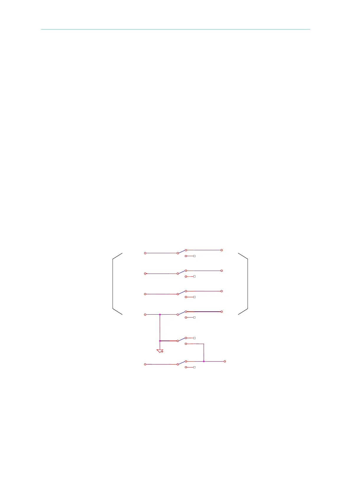
(2) When CHANNEL 3 is set L (low):
(a) Start test: The HV OUTPUT terminal on the rear panel and the
DRIVE- on front panel are connected. The DRIVE and SENSE
terminals on the front panel are disconnected from the DRIVE and
SENSE terminals on rear panel as shown below: