Descriptions of Panel
4-27
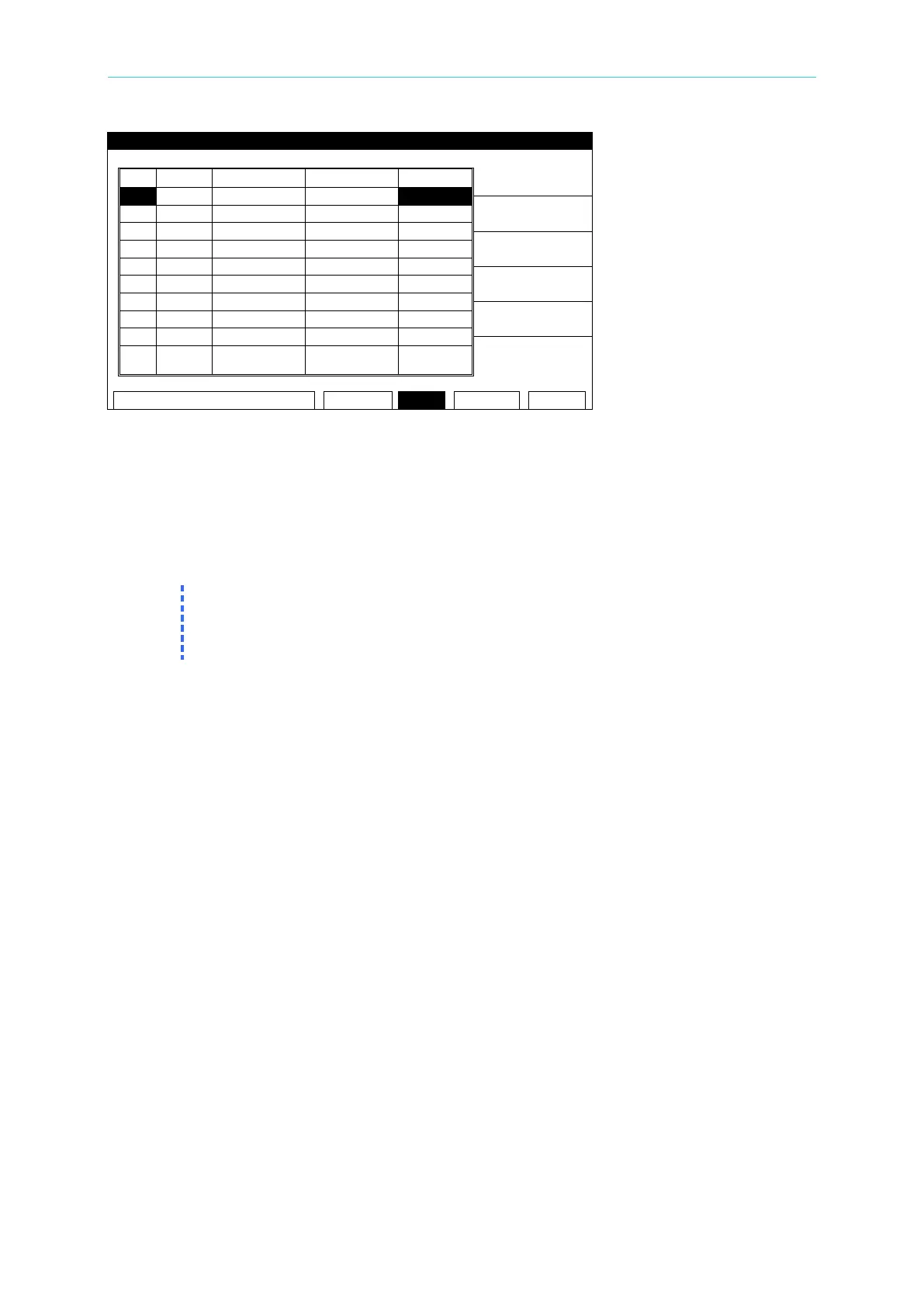
Figure 4-11
5. Press the [STOP] key then [UNLOCK] to clear the buzzer sound. The display will show
the “UNLOCK” window.
6. Using the numeric keys, input the PASSWORD [0] [0] [0] [0] (or the NEW SECURITY
CODE if it is set).
7. Press the [START] key to restart the test.
8. Press [MENU] to return to the MAIN MENU.
1. If the User Password has been changed, [0][0][0][0][ENTER] will not work for FAIL
LOCK. Use the new User Password.
2. When the 19032 is powered down with FAIL LOCK ON, it will boot to the TEST menu
4.13.2 Release FAIL LOCK
1. When the title list displays “MAIN MENU”, press the numeric key which corresponds to
FAIL LOCK [6] to display the “RELEASE FAIL LOCK” window.
2. Using the numeric keys, input the PASSWORD [0] [0] [0] [0] (or the NEW SECURITY
CODE if it has been set).
3. Press the [ENTER] key. The FAIL LOCK function will be turned off and the display will
show the “LOCK” window.
4.14 Remote Control
This analyzer has two terminal strips and a 9 pin D-series connector on the rear panel for
remote control. There is a black 6 screw relay strip for the remote output signals: UNDER
TEST, PASS, & FAIL. There is a black 5 screw relay strip for the remote input connections:
START, RESET, COM, & INTER LOCK. Inputs require a contact closure and outputs provide
a contact closure, as shown in Figure 4-15. To control this analyzer with an external signal,
connect the signal cable to the appropriate terminal. Remote control is generally controlled by
the high voltage probe; however, other control circuits can also be used to control it instead.
The test bar is the switch for controlling the high voltage output, so the connected control wire
should not be near the high voltage site and test cable to avoid causing any hazard.