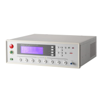
Panel Description
Control external signal by using this short condition. The junction
specification 115V AC current is lower than 0.3A action time.
This tester is under testing status until STOP is stopped.
PASS : When the tester judge DUT is PASS, this output terminal is short circuit.
Control external signal by using this short circuit condition. The junction
specification 115V AC current is lower than 0.3A.
The action time is 0.2sec ∼ 99.9sec. (Can be set)
FAIL : When the tester judge DUT is FAIL, this output terminal will be short circuit.
Control external signal by using this short condition. The junction
specification 115V AC current is lower than 0.3A.
The action time: From judging FAIL to STOP is stopped.
OUTPUT Switch: When toggles this switch to power symbol, UNDER TEST output
terminal will be short circuited under test status. When toggles this
switch to voltage symbol, UNDER TEST terminal outputs 24V under
test status. This function can be used with 3002B or 3002D and is for
controlling valve.
2. VOLTAGE SELECTOR Input Power Supply Range Switch
Changing the tester inputted AC power. Using AC power has four kinds as below.
a. 90 ∼ 110V AC
b. 108 ∼ 132V AC
c. 198 ∼ 242V AC
d. 216 ∼ 250V AC
Switching this power switch by applying AC power and notice the change of fuse.
3. AC LINE: AC power socket and fuse holder.
A tri-cord power and fuse holder. Input AC power, which the tester is needed from AC
power socket. The detailed specification of using fuse please refers "Chapter 3 - Notice
Items Before Using" or descriptions of rear panel in this manual.
4. GROUND: Safety GND terminal. Please use adaptable implement to connect this
grounding terminal actually. If there is no grounding actually, the circuit with GND
terminal or other instruments connecting cable with GND terminal is short circuit. The
cover of tester may exist high voltage. This is very dangerous, anyone touch the tester
under the above status may cause damage. Therefore, it is necessary to connect
safety GND terminal to ground.
5. GPIB INTERFACE (Option)
This socket is for optional GIPB interface (IEEE-488-1978). The detailed descriptions,
please refers "Chapter 5 - Description of GPIB Interface" in this manual.
6. OPTION: This socket is the option PRINTER interface for the tester. The detailed
descriptions please refer chapter 8 of this manual.
7. FAN: The temperature control fan.
When the temperature reaches 50°C, fan opens automatically. When the temperature is
lower than 45°C, fan stops automatically.
8. 9 Pin D Connector
All of 9 pin D-Sub connector functions are the same as (1) Remote I/O.
9. RS232 Interface
This socket is the standard RS232 interface for the tester. GPIB and RS232 interface
can’t use simultaneously.
4-3
www.valuetronics.com