Panel Description
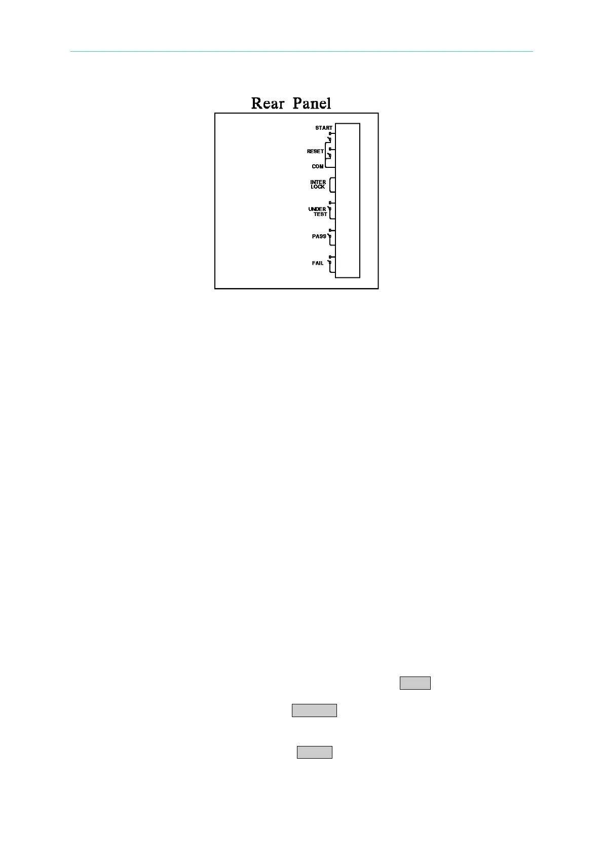
Figure 4-4
4.12 Output Signal
The tester includes LED and buzzer two kinds of indication signal. The rear panel of tester
has the following output signals.
UNDER TEST : When the analyzer is under test, the output terminal will short circuit.
Users can use this short condition to control external signal. The junction
specification 115V AC current is lower than 0.3A.
PASS : When the tester judge DUT is good, the output terminal will short circuit.
Users can use this short circuit condition to control external signal. The
junction specification 115V AC current is lower than 0.3A.
The action time is 0.2sec ∼ 99.9sec. can be set.
FAIL : When the tester judge DUT is no good, the output terminal will short circuit.
Users can use this short circuit condition to control external signal. The
junction specification 115V AC current is lower than 0.3A.
The action time: from judge as no good to STOP is stopped.
4.13 Scan Test
The tester multipoint scans on DUT (only 19053/19054) for more faster and effective test.
Setting method:
1. Enter test parameter setting menu and setting test parameter in sequence.
2. When the highlighted position on “SCAN”, press Function Key MOVE can select the
output channel want to set. (19053: 1 ∼ 8 / 19054: 1 ∼ 4)
3. At the same time, can use Function Key CHANGE to set the status of scanning test
output terminal. Press this key will shows “H”, “L” and “X” in sequence, it means do
output from High Channel; do output and don’t output from Low Channel.
4. Setting is completed, press Function Key ENTER to confirm and exit.
4-19
www.valuetronics.com