HIPOT Tester 19051/19052/19053/19054 User’s Manual
of controlling high voltage output. Be careful that the control cables don’t close high voltage
terminal and test cables to avoid dangerous.
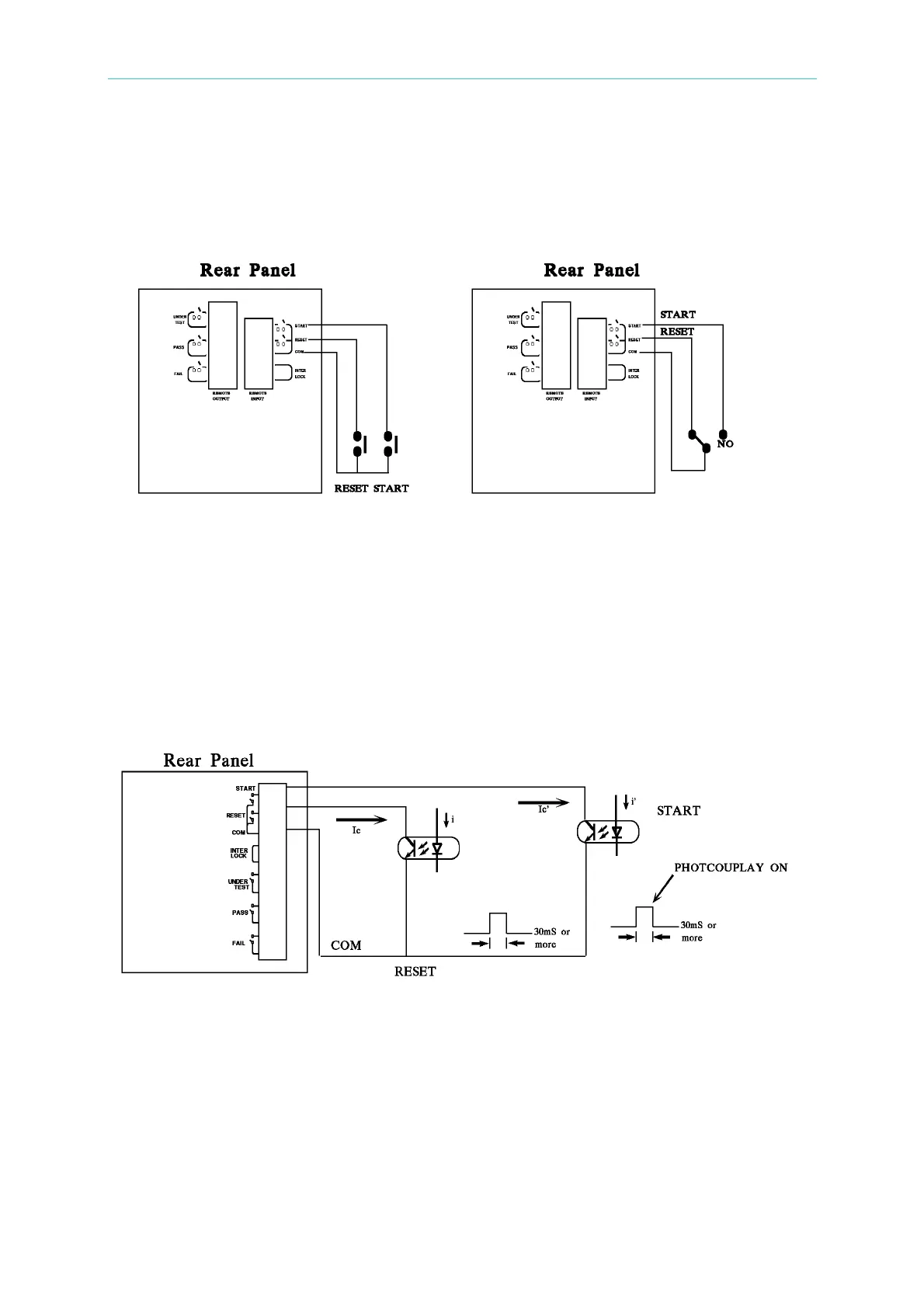
1. If users want to control START single and STOP signal can refer to Figure 4-1. As this
figure described method connect to REMOTE position on front panel.
Figure 4-1 Figure 4-2
2. As Figure 4-2, the main unit is under STOP status. NC point is connecting to STOP and
NO point connecting to START.
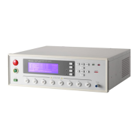
3. Some logical components such as transistor, FET, coupler. Also can be used to
connect as control circuit as Figure 4-3. The connecting signal and circuit as Figure 4-3.
Only the circuit includes the following statuses, it can control the main unit.
(1) The signal of LOW flows current is 2mA or less.
(2) The action time of inputting signal should over 20mS.
Figure 4-3
4. The relay switch control as Figure 4-1 and photo-coupler control as Figure 4-3 are
controlled by component contact. It is effective to avoid error operation system cause
by interference. Although the main unit has a lot of preventions, it is necessary to be
careful that interferences result from setting measurement system.
5. Pin diagram of REMOTE CONTROL as Figure 4-4. When users want to control by
external, please remember this pin diagram.
4-18
www.valuetronics.com