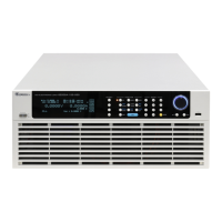
High Power Electronic Load 63200A Series Operation & Programming Manual
Table of Contents
1. Overview ................................................................................................................... 1-1
Introduction ......................................................................................................... 1-1 1.1
Description .......................................................................................................... 1-1 1.2
Features ............................................................................................................. 1-1 1.3
Specifications ...................................................................................................... 1-2 1.4
Dimensions of 63200A Series Electronic Loads .................................................. 1-6 1.5
2. Installation ................................................................................................................ 2-1
Introduction ......................................................................................................... 2-1 2.1
Inspection ........................................................................................................... 2-1 2.2
Installing the Communication Interface Expansion Slot ....................................... 2-2 2.3
Line Voltage ................................................................................................ 2-2 2.3.1
Turn-On Self-Test ....................................................................................... 2-3 2.3.2
Application Connection ....................................................................................... 2-3 2.4
Load Connections ....................................................................................... 2-3 2.4.1
Vsense Remote Sensing Connections ........................................................ 2-5 2.4.2
Parallel Connection ..................................................................................... 2-6 2.4.3
Remote Control Connection ................................................................................ 2-6 2.5
Maintenance & Cleaning ..................................................................................... 2-7 2.6
Calibration & Verification ..................................................................................... 2-7 2.7
3. Operation Overview .................................................................................................. 3-1
Introduction ......................................................................................................... 3-1 3.1
Front Panel ......................................................................................................... 3-1 3.2
VFD ............................................................................................................. 3-2 3.2.1
HOTKEY ..................................................................................................... 3-3 3.2.2
Function Keys ............................................................................................. 3-3 3.2.3
Arrow Keys & Push Button Rotary ............................................................... 3-4 3.2.4
Rear Panel .......................................................................................................... 3-4 3.3
Voltage & Current Monitoring (V/I Mon) ....................................................... 3-5 3.3.1
System Bus Port ......................................................................................... 3-5 3.3.2
DIGITIAL IO ................................................................................................ 3-6 3.3.3
Extended Communication Interface ............................................................ 3-7 3.3.4
USB Remote Control ................................................................................... 3-8 3.3.5
Local/Remote Control ......................................................................................... 3-8
3.4
Configure ............................................................................................................ 3-8 3.5
Load Setup .................................................................................................. 3-9 3.5.1
Measurement ............................................................................................ 3-11 3.5.2
Parallel & Sync. ......................................................................................... 3-11 3.5.3
GO/NG Spec. Testing ............................................................................... 3-12 3.5.4
Customized Protection .............................................................................. 3-14 3.5.5
Setting Remote Communication Interface ................................................. 3-14 3.5.6
System Setup ............................................................................................ 3-14 3.5.7
Basic Operation Modes ..................................................................................... 3-15 3.6
Constant Current Mode ............................................................................. 3-16 3.6.1
Constant Resistance Mode ....................................................................... 3-17 3.6.2
Constant Voltage Mode ............................................................................. 3-18 3.6.3
Constant Power Mode ............................................................................... 3-19 3.6.4
CCD Mode ................................................................................................ 3-21 3.6.5
CRD Mode ................................................................................................ 3-22 3.6.6
Advance Mode .................................................................................................. 3-23 3.7
BATT (Battery Discharge Timer) ............................................................... 3-24 3.7.1

 Loading...