High Power Electronic Load 63200A Series Operation & Programming Manual
The chassis is grounded through the 3
rd
pin of power cord. Be sure the
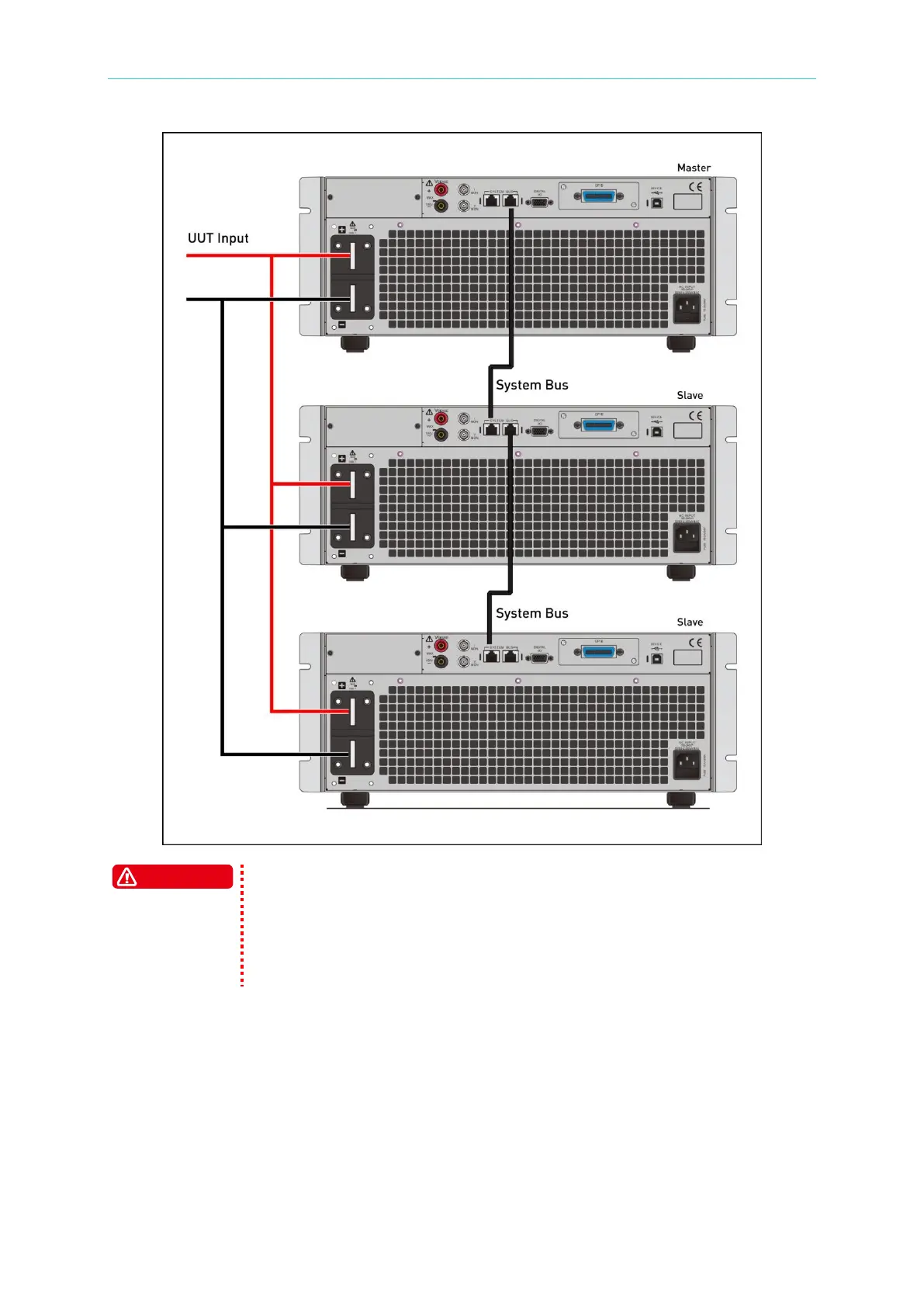
power socket is 3-pin type and the pin is properly grounded. The
parallel cable is a standard Chroma accessory. Do not use the cable of
other brand to avoid damaging the equipment. The System Bus is a
parallel connecting port of 63200A Series Electronic Load; do not
connect it with other devices to avoid damaging the equipment.
DIGITIAL IO 3.3.3
The IO port is a 15-pin D-SUB male connector on the rear panel of 63200A Series Electronic
Load. It contains 0-10V
DC
external input analog signals and digital I/O signals. The digital
I/O signals are TTL compatible and defined as below:

 Loading...