EN-8
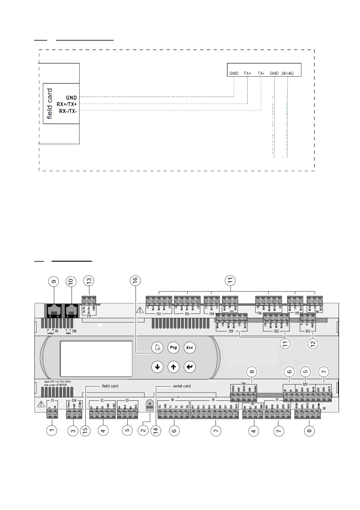
1.3.4 Electrical connections
The room terminal and the controller are electrically connected using an AWG20/22 shielded cable (not supplied)
comprising two twisted pairs.
The first and last controller must be no more than 500m apart. This network must never run parallel to power cables at
a distance of less than 50 cm. These cables may cross, but perpendicularly. You are requested not to form a loop
with the network cable or the earth braid, and to properly separate the various cable families (control, power, earth
and communication bus).
In case of transmission problems, it is vital to connect a 120Ω ¼W electrical resistor between terminals TX+ and TX-
of the room terminal, as indicated in the manual supplied with the room terminal.
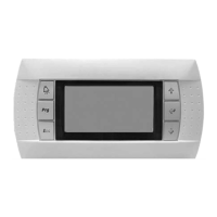
1.4 The controller
The descriptions of the terminals on the controller are provided below.
1. power supply connector [G(+), G0(-)]
2. Yellow power LED and red alarm LED
3. additional power supply for terminal and 0-5 V ratiometric sensors
4. NTC, 0-5V, 0-10V universal analogue inputs
J11 terminals
To terminal 4 Connector 19
To terminal 2 Connector 19