EN-6
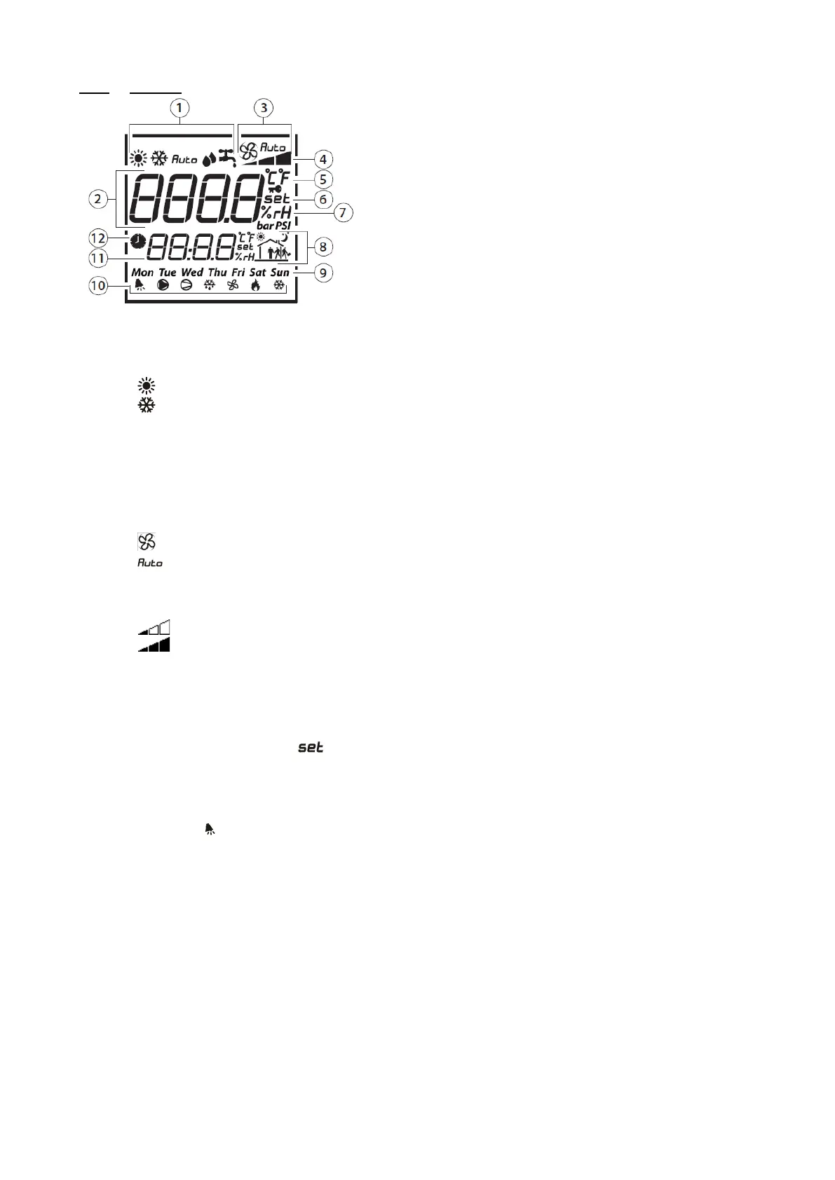
1.3.2 Displays
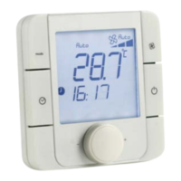
1. Unit operating mode
2. Main display area
3. Ventilation operating mode
4. Ventilation operating speed
5. Temperature unit
6. Indicates whether the value displayed in the main area
is a setpoint
7. Indicates whether the value displayed in the main area
is a humidity
8. Area not used
9. Day of the week
10. Operating icons
11. Secondary display area
12. Run time range mode
Details:
1. Unit operating mode
- : Unit in heating mode
- : Unit in cooling mode
2. Main display area
- Displays "OFF" when the unit is switched off manually via the room terminal
- Displays the ambient temperature
- Displays the temperature setpoint when the encoder is turned
- Displays the various menus during browsing
- Displays the various setting parameters
3. Ventilation operating mode
- : Indicates that the ventilation is active and in setpoint-based flow or Supply air duct pressure mode.
- : Indicates that the ventilation is in automatic mode based on the regulated temperature.
- No display: the unit has been switched off by the HMI terminal, by a major fault or to Standby by a time
program.
4. Ventilation operating speed
- : The ventilation is operating at reduced flow or Eco Supply air duct pressure
- : The ventilation is operating at a nominal flow rate or Comfort Supply air duct pressure
5. Temperature unit
- °C: temperature expressed in degrees Celsius
- °F: temperature expressed in degrees Fahrenheit (not used)
6. Indicates whether the value displayed in the main area is a setpoint
After the encoder has been turned and then pressed, it is possible to modify the temperature setpoint
characterised by the indicator .
7. Area not used
8. Area not used
9. Area not used
10. Operating icons
Only the bell is used. It indicates the presence of a fault. This icon is inhibited when the faults are cleared
via the HMI terminal.
11. Secondary display area
Displays the time on the controller. This area can also be used for modifying the controller time.
12. Run time range mode