EN-52
5.4 LON
The communication card is supplied preloaded. The information data is retrieved via the CMS using a shunt on the
Pin Service on the front panel of the expansion board.
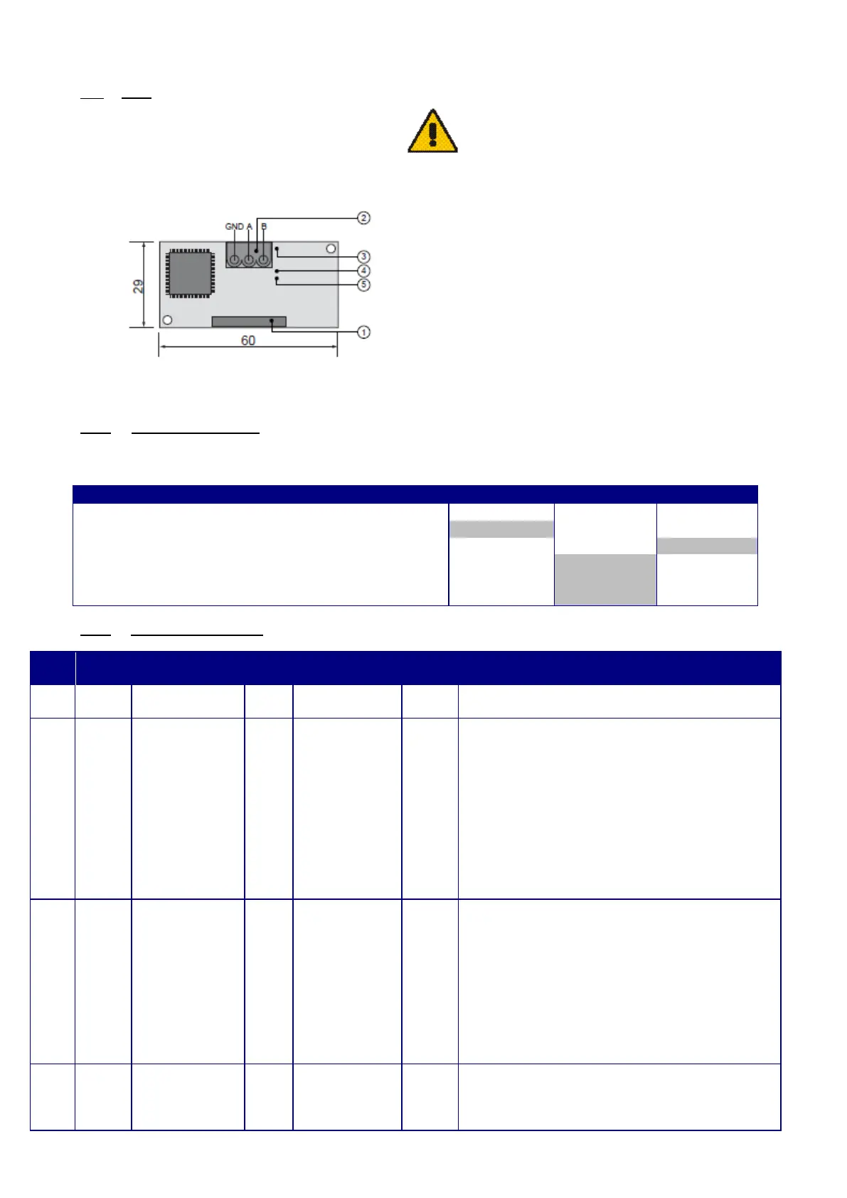
1. Connector for the controller
2. Disconnectable terminal for connection of the
LonWorks® network (GND, A, B)
3. Pin service
4. Green service LED: state of the node, lit
during the pin service, flashing when the board
receives a command from the network, if
permanently lit = board faulty
5. Red fault LED: signals a board installation
problem (connection, communication speed
On request, the file "Air_Technologies_110905.XIF" (Program ID: 90:00:94:82:00:0A:04:01) is available.
5.4.1 LON scope of supply
Recap of on-site LON tasks by Manufacturer/Installer/Integrator for system start-up:
Supply of .XIF integration file
Installation of units equipped with LON controller
Addressing and configuration of LON network
Definition of master/slave zones
Definition of setpoints and time programs
5.4.2 The digital datapoints
Type Index NV name
Description
Unit On/Off command via CMS
Unit On/Off command return via CMS
Supply air fan monitoring input
Return air fan monitoring input
Electric pre-heater safety check input
Electric heater safety check input
Changeover thermostat input
Presence detection or Remote Control input
Non-critical fault output
Damper control output (frost-protection or insulating)
External generator control output (boiler or heat pump)
Electric heater stage 1 control output
Electric heater stage 2 control output
Humidifier control output
Return air filter clogged alarm
Supply air filter clogged alarm
Return air filter dirty alarm