EN-14
Connector J10
6-channel connection for a standard user HMI
Connector J11
Rx-/Tx- RS485 link for the pLAN network
Rx+/Tx+ RS485 link for the pLAN network
GND RS485 link for the pLAN network
Connector J23 Not used
1.10.3 Reversal depending on the unit type
Unit type CLASSIC RHE CLASSIC VERTICAL CEILING UNIT
Supply air temp.
sensor
J3-B4 J3-B4 J3-B4 J3-B5
Return air temp.
sensor
J20-B9 J3-B5 J3-B5 J3-B4
Fresh air temp.
sensor
J3-B5 J20-B9 J20-B9 J20-B9
Qv supply air
pressure sensor
J2-B3 J2-B3 J2-B2 J2-B2
Qv return air pressure
sensor
J2-B2 J2-B2 J2-B3 J2-B3
Return air filter fouling
pressure sensor
J2-B1 J6-B8 J6-B8 J6-B8
Supply air filter fouling
pressure sensor
J6-B8 J2-B1 J2-B1 J2-B1
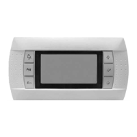
2 Overview of the screens
2.1 Menu or Esc button
"Prg" button
U:00 Indicates the unit's address
Indicates the request to switch the machine on or off
Indicates the presence of an hourly or annual time schedule and the request status
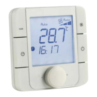
00.0°C Indicates the regulated temperature (ambient, return or supply air)
00:00 Time
Off Indicates the status of the unit: Off, Damper open, On, On after power failure,
Standby, Switched off by fault, Switched off by CMS, Post-ventilation, Manual Mode
Indicates "Pre-heating" operating mode
Indicates "Heating" operating mode
Indicates the "Cooling" operating mode
Indicates Fire alarm