GE+ ACDC Installation and operation manual v11
100 / 121
II. AC Faults
Before introducing any fault to the emulated grid, some grid must be created and there are two
ways to do so: from the “AC Operation” tab (chapter 1.5.1) or the “AC Faults” tab (explained in
this chapter).
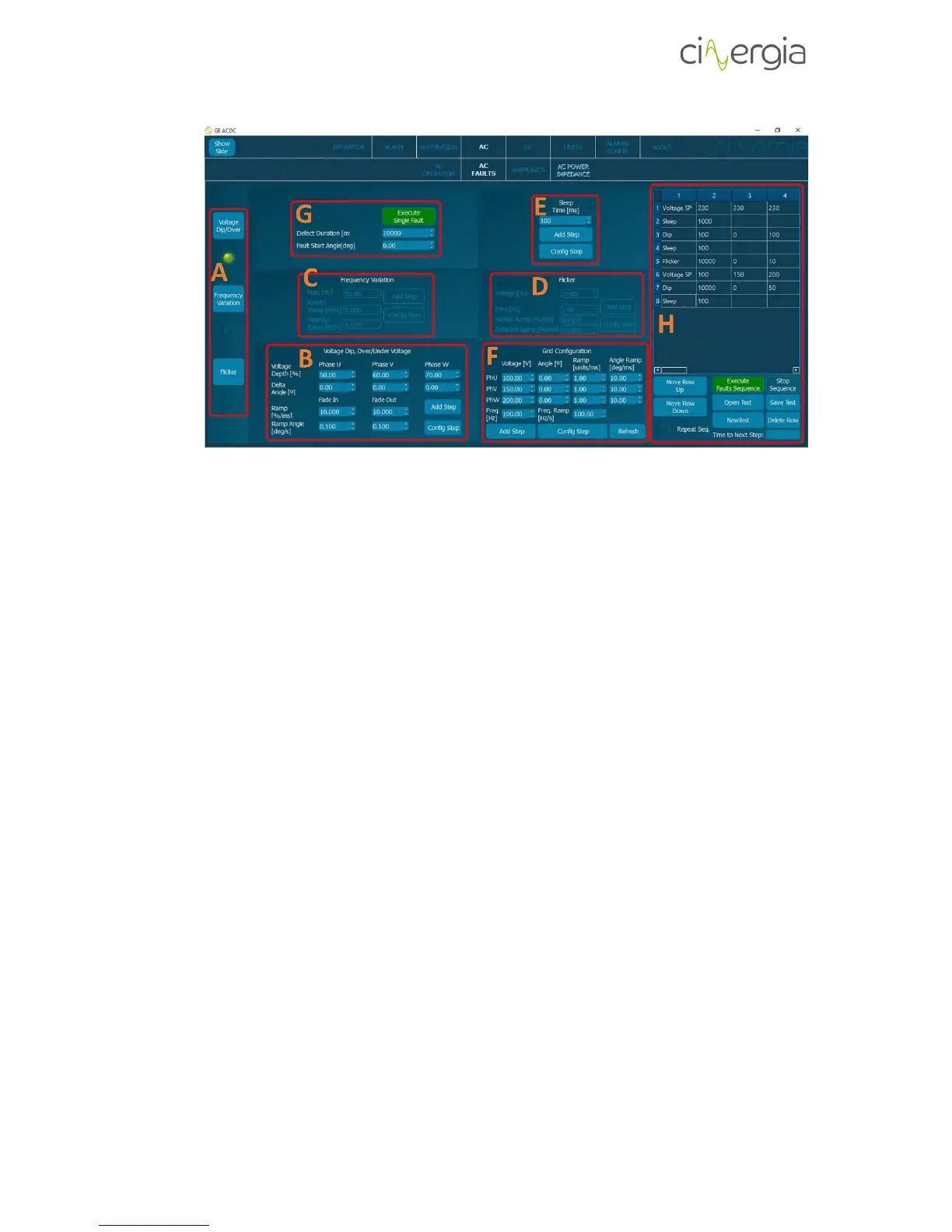
- A: Selection of the fault. By selecting each fault, the corresponding part is going to be
illuminated.
- B: Voltage Dip and Over/Under Voltage configurations. Introduce the percentage of the
voltage and the angle of each phase. Note that 0% means 0V and 50% is the half of the
current voltage. A Delta Angle of Xº means that the phase will start the fault Xº after the
U channel. There are also ramps for the voltage and the angles. The buttons Add Step
and Config Step are explained at the point H of this chapter.
The following images illustrate the same voltage dip with different Delta angle (the
channels are U-yellow, V-green and W-purple):