GE+ ACDC Installation and operation manual v11
15 / 121
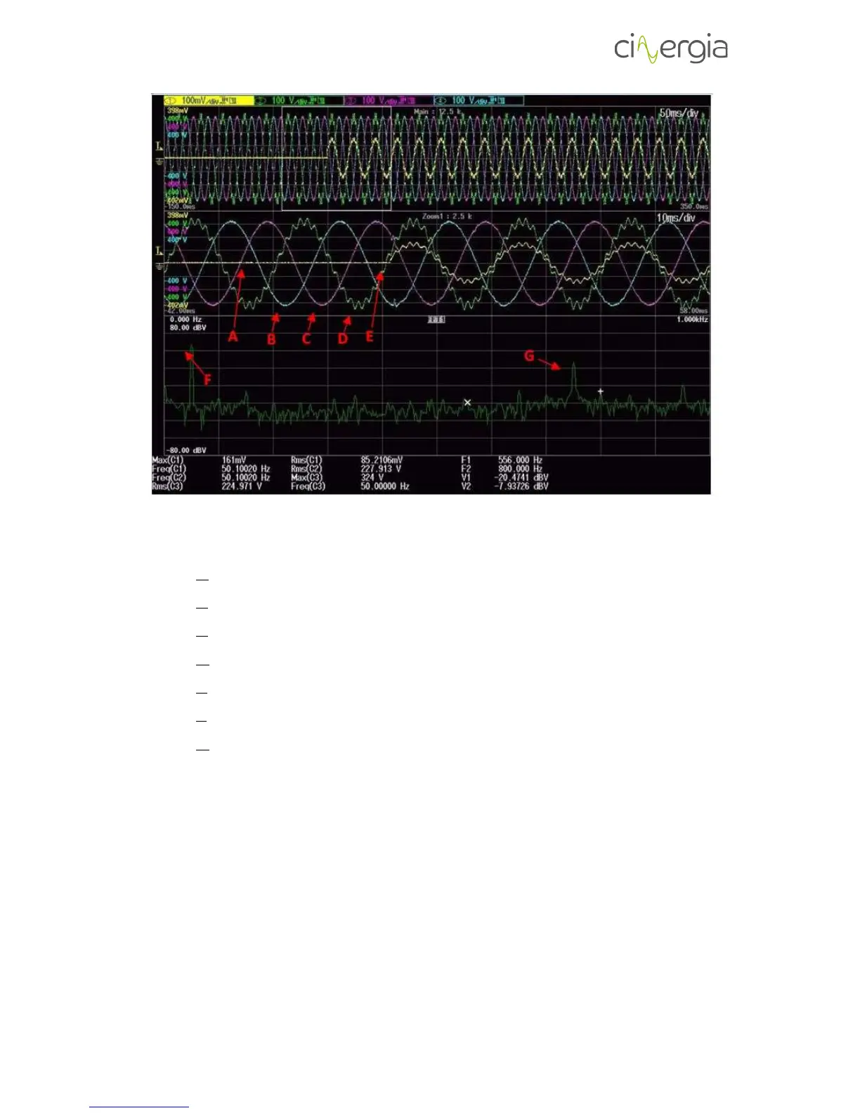
Where:
- A: EUT current (EUT is connected to the phase W of GE)
- B: GE output voltage U
U-N
- C: GE output voltage U
V-N
- D: GE output voltage U
W-N
- E: Instant at which the EUT is started.
- F: Fundamental harmonic of U
W-N
(shown in the FFT)
- G: 15
th
harmonic of U
W-N
(shown in the FFT)
II. PID control (only in DC mode)
For those cases in which DC output option is chosen for the grid emulator, the EUT side control
algorithm is based on a traditional PID controller.