GE+ ACDC Installation and operation manual v11
43 / 121
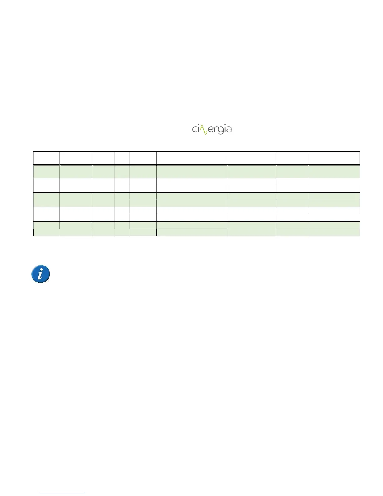
DC U1 Power DC setpoint min power 0 max power
DC U1 Resistance not used 10000 0
Voltage
source
Independent Bipolar DC
U1 Voltage U DC bipolar setpoint min bipolar voltage 0 max bipolar voltage
W1 Voltage W DC bipolar setpoint min bipolar voltage 0 max bipolar voltage
Current
source
Independent Bipolar DC
U1 Current U DC bipolar setpoint min current DC 0 max current DC
W1 Voltage W DC bipolar setpoint min current DC 0 max current DC
Power
source
Independent Bipolar DC
U1 Power U DC bipolar setpoint min power 0 max power
W1 Power W DC bipolar setpoint min power 0 max power
Impedance
Independent Bipolar DC
U1 Resistance U DC bipolar setpoint not used 10000 0
W1 Resistance W DC bipolar setpoint
not used 10000 0
Table 2 Range value of each input analogue depends on the control of the equipment (AC/DC, independent/parallel, V/I/P/R, Bipolar/Unipolar)
The table above is valid for all the equipment of CINERGIA (AC and DC current, voltage, power and impedance control)