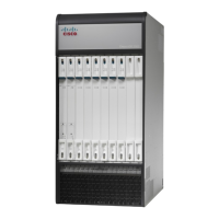
Lowering the Cable Management Tray
Step 1
At the rear of the chassis, apply slight upward pressure at the base of the cable management tray.
Step 2
Flip the latches on the swing arms upward and free of the posts.
Step 3
Lower the tray until it rests against the chassis.
Step 4
If you are removing an MIO/UMIO card, refer to Detaching Network Cables from the Card Bracket, on page 165.
Otherwise, remove the circuit card as described in the Remove and Replace the Circuit Card section of the Replaceable
Components chapter.
Step 5
Proceed to Raising the Cable Management Tray, on page 166.
Detaching Network Cables from the Card Bracket
Step 1
Cut the nylon cable ties or open the hook-and-loop straps that secure network cables to the MIO/UMIO card.
Step 2
Unplug the cable connectors starting from the top ports.
The ends of all network cables should be labeled with their slot/port terminations. If this has not been done,
you should label each cable as you disconnect it.
Important
Step 3
Move the cable bundles away from the MIO/UMIO. You may have to re-open the hook-and-loop straps in the cable
management tray to free the cables.
Step 4
Remove the MIO/UMIO card as described in Remove and Replace the Circuit Card section of the Replaceable Components
chapter.
Never use the cable management bracket as a "handle" to remove or lift an MIO/UMIO. The bracket is not
designed to support the weight of an MIO/UMIO.
Caution
Reconnecting Network Cables to the Card Bracket
Step 1
The replacement MIO/UMIO card should have a cable management bracket pre-installed as described in Installing Cable
Management Brackets, on page 160
Step 2
Route the cables and secure them to the bracket as described in Routing and Securing Network Cables, on page 162
Step 3
Proceed to Raising the Cable Management Tray, on page 166
ASR 5500 Installation Guide
165
Cable Management System Installation
Lowering the Cable Management Tray

 Loading...


